
Efficient concentrator
A concentrator, high-efficiency technology, applied in the direction of multi-effect evaporation, evaporator accessories, etc., can solve the problems of increasing production cost, reducing evaporation effect, and deteriorating concentration effect.
Patent Information
- Authority / Receiving Office
- CN · China
- Patent Type
- Applications(China)
- Current Assignee / Owner
- Publication Date
- 2016-11-16
Smart Images
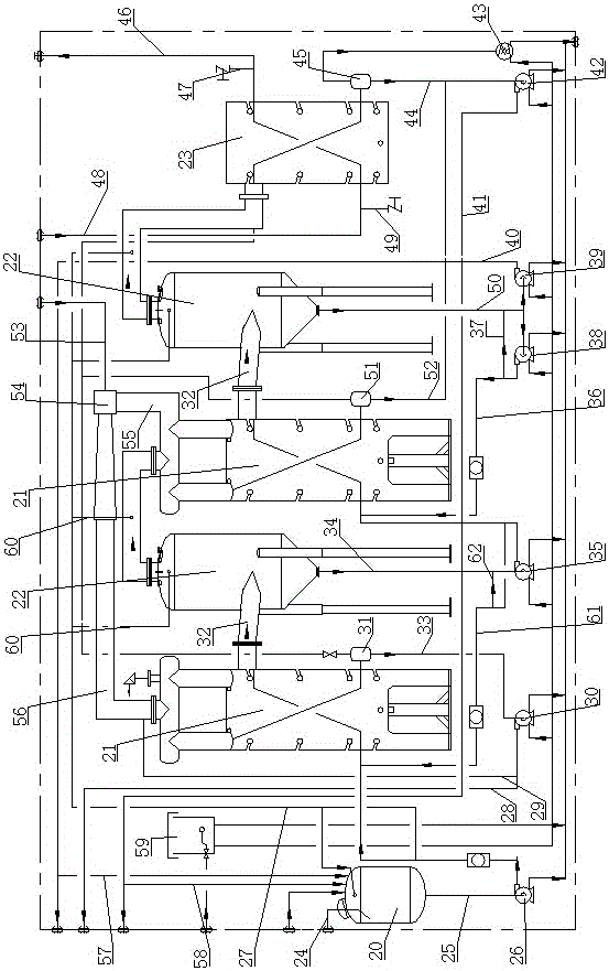
Figure 1 
Figure 2 
Figure 3
Abstract
Description
technical field
[0001] The invention relates to a high-efficiency concentrator. Background technique
[0002] In large-scale industrial production, it is often necessary to evaporate a large amount of water, which requires a large amount of energy to heat the raw material to heat the water in it to form steam. In order to reduce the consumption of heating steam, multi-effect evaporation can be used. The heating steam is passed into the first evaporator, the raw material is heated and boils, and the secondary steam generated by the evaporation of the raw material is used as heating steam and introduced into the next evaporator, as long as the pressure of the latter evaporation chamber and the boiling point of the solution are higher than those in the original evaporator. If it is low, the introduced secondary steam can act as a heating source. Similarly, the new secondary steam generated by the second evaporator can be used as the heating steam of the third evaporator. In ...
Examples
Embodiment Construction
[0027] The high-efficiency concentrator includes a balance tank 20, a separation device, and a plate condenser 23. The feed port of the balance tank 20 is connected with a feed pipe 24, and the discharge port of the balance tank 20 is connected with a discharge pipe 25, and the discharge pipe 25 is installed There is a liquid inlet pump 26, wherein the separation device includes a plate evaporator 21 and a separation tank 22, the steam inlet of the plate evaporator is connected with a steam inlet pipe 56, and the raw material outlet of the plate evaporator is connected with the inlet of the separation tank through a separation pipe 32, separating The pipe is arranged tangentially to the separation tank, and the separation pipe is inclined downward from the feed end to the discharge end, so that the material flows into the separation tank smoothly.
[0028] The separation device in the present invention is two groups or more than two groups, and its pipeline connection structure...