
Splitting type laminar flow constant interfacial cell and extraction method

A constant interface, split-type technology, applied in the direction of liquid solution solvent extraction, etc., can solve the problems of unrealized mixing and drainage, leakage, interphase contact, poor applicability, etc., to ensure interface stability and eliminate diffusion. Influence, promotional effect

Inactive Publication Date: 2016-11-16
INST OF PROCESS ENG CHINESE ACAD OF SCI
View PDF4 Cites 0 Cited by
  • Summary
  • Abstract
  • Description
  • Claims
  • Application Information

AI Technical Summary

Problems solved by technology

However, the shortcomings of this type of laminar flow constant interface tank are also very obvious, because the selection of the stirring impeller, structural size, installation position, etc. affect the flow field of the stirring chamber in the laminar flow constant interface tank and the suction of the stirring impeller, while The position of the deflector affects the flow field structure of the light phase or heavy phase in the laminar constant interface tank
If the design and type selection or installation position of the stirring impeller is improper, its mixing and drainage effects will not be realized.
However, the selection and installation position of the stirring impeller needs to rely on a large number of experimental verifications or a large number of simulation calculation verifications, and the applicability to different extraction reaction systems is not good.
At the same time, this type of laminar flow type constant interface tank, due to the existence of light phase deflectors, has to be replaced by side insertion, which leads to the leakage of light and heavy phases in the constant interface tank, which causes mutual phase contact. error

Method used


Image

  • Splitting type laminar flow constant interfacial cell and extraction method
  • Splitting type laminar flow constant interfacial cell and extraction method
  • Splitting type laminar flow constant interfacial cell and extraction method

Examples


Embodiment 1

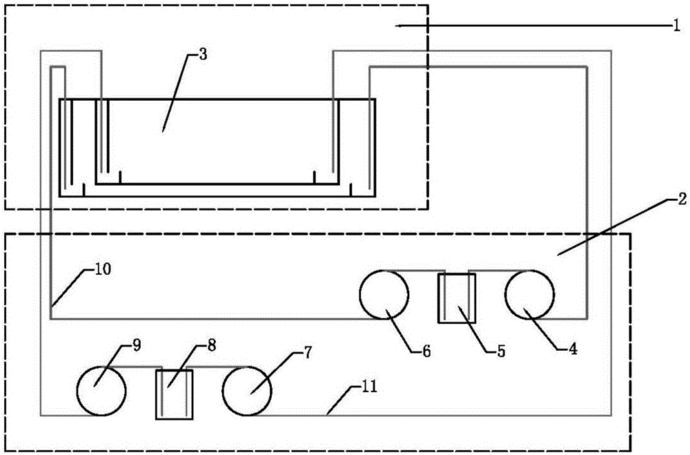
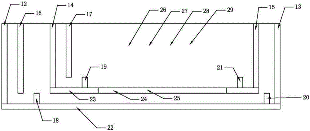
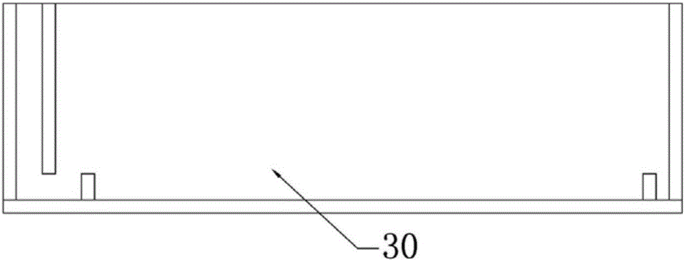
[0084] A kind of split type laminar flow constant interface pool 3 (such as Figure 1-Figure 4 shown), including laminar flow constant interface tank main body 1 and auxiliary system 2;

[0085] The main body 1 of the laminar flow constant interface tank includes a heavy phase liquid tank for placing the heavy phase and a light phase liquid tank for placing the light phase; the bottom plate of the light phase liquid tank is provided with a first through hole 24, and the heavy phase and the light phase pass through The first through hole 24 realizes laminar constant interface extraction;

[0086] The auxiliary system 2 includes a heavy phase auxiliary system and a light phase auxiliary system, the heavy phase auxiliary system is connected with the heavy phase liquid tank, and is used to input the mixed heavy phase into the heavy phase liquid tank, and extract the heavy phase after the extraction reaction takes place. The heavy phase is extracted; the light phase auxiliary syst...

Embodiment 2

[0099] A split type laminar flow constant interface pool 3, the structure of the split type laminar flow constant interface pool 3 is the same as that of the split type laminar flow constant interface pool 3 described in Example 1, the difference lies in:

[0100] The light phase liquid level stabilizing plate 17 of described light phase liquid tank is positioned at the right side of light phase liquid tank, and described heavy phase liquid level stabilizing plate 16 is positioned at the left side of heavy phase liquid tank (as Figure 5 b).

[0101] According to the different sizes of the light phase liquid tank and the heavy phase liquid tank, the size of the first through hole can be different from Figure 9 , the size of the interface plate and the size of the second through hole can also be different from the Figure 10 . Can be designed according to actual needs.

Embodiment 3

[0103] Using the split type laminar flow constant interface pool 3 described in embodiment 1, according to figure 1 Build a split laminar flow constant interface pool. The kinetic determination test of trivalent erbium in the P507-kerosene extraction hydrochloric acid system was carried out in the main body 1 of the laminar flow constant interface pool. The erbium ion hydrochloric acid solution with pH=3.0 was used as the water phase, and the 1.52mol / L P507-kerosene solution was used as the oil phase. The specification of the interface board used in the experiment is 70mm×140mm, and the specification of the second through hole on the interface board is 50mm×30mm, such as Figure 10 shown in d. Use the heavy phase extraction pump 4 to extract the water phase into the heavy phase mixing chamber 5 with a 500mL beaker. After the water phase is stirred, the heavy phase injection pump 6 injects the water phase into the front end of the heavy phase liquid tank of the laminar flow ...


PUM


Abstract

The invention provides a splitting type laminar flow constant interfacial cell and an extraction method. The splitting type laminar flow constant interfacial cell comprises a laminar flow constant interfacial cell main body and an auxiliary system; the laminar flow constant interfacial cell main body is used for carrying out laminar flow constant interfacial extraction on a light phase and a heavy phase; the auxiliary system comprises a heavy-phase auxiliary system and a light-phase auxiliary system; the heavy-phase auxiliary system is connected with a heavy-phase liquid groove and is used for inputting the uniformly-mixed heavy phase into the laminar flow constant interfacial cell main body and pumping out the heavy phase subjected to an extraction reaction; the light-phase auxiliary system is connected with a light-phase liquid groove and is used for inputting the uniformly-mixed light phase into the laminar flow constant interfacial cell main body and pumping out the light phase subjected to the extraction reaction. The splitting type laminar flow constant interfacial cell can be used for eliminating influences caused by diffusion and can also ensure a stable interface between the light phase and the heavy phase; influences, caused by a traditional constant interfacial cell, on model selection and installation position of a stirring paddle do not need to be considered; the splitting type laminar flow constant interfacial cell is easy to operate, simple in structure and convenient to machine and manufacture and is beneficial to popularization.

Description

technical field [0001] The invention belongs to the technical field of extraction kinetics research equipment, and in particular relates to a split type laminar flow constant interface pool and an extraction method. Background technique [0002] Constant interface cell is one of the equipments for studying extraction chemical reaction kinetics. The study of extraction chemical reaction kinetics can provide necessary information for the structure and size of extraction equipment. [0003] Since Lewis proposed the constant interface pool method to study the kinetics of extraction chemical reactions, two types of constant interface pools have emerged: [0004] The first type of constant interface pool is represented by literature (Chemistry Bulletin, No. 2, 1988, P32, etc.). Two layers of stirring paddles are installed on the upper and lower parts of the same stirring shaft. Insert this stirring shaft into a container filled with immiscible light and heavy phases, the upper ...

Claims


Application Information

Patent Timeline
Patent Type & Authority Applications(China)
IPC IPC(8): B01D11/04
CPCB01D11/04
Inventor 黄焜肖传绪刘会洲
Owner INST OF PROCESS ENG CHINESE ACAD OF SCI
Learn More