Kitchen waste treatment device

A treatment device and technology for food waste, which is applied in grain treatment, irradiation, etc., and can solve problems such as blockage of waste discharge outlets, high oil content, and high nutritional content of food waste.

Inactive Publication Date: 2016-11-16
霍普科技(天津)股份有限公司
View PDF6 Cites 7 Cited by
  • Summary
  • Abstract
  • Description
  • Claims
  • Application Information

AI Technical Summary

Problems solved by technology

Due to the characteristics of high oil, high salinity, and high nutritional content of food waste in my country, and the complex components contained in it, there are two problems in the anaerobic fermentation of biogas: one is that the food waste has more nutrients, and the hydrolysis acidification stage produces There are more acids, which is not conducive to the subsequent biogas production by methanogenic bacteria; second, the carbon-nitrogen ratio of food waste in my country is uncoordinated, the nitrogen content is high, and there are many impurity inhibitors, which are not conducive to the adoption of anaerobic biogas production technology.
At present, landfill is the main way to deal with urban waste, but this way occupies land and poses a serious threat to the environment, especially groundwater resources; incineration can reduce waste by about 90%, but it requires a large one-time investment, high operating costs, and recyclable resources Waste, air pollution is more serious; due to too few grinding stages, all garbage is not sufficiently ground, and the diameter of the particles after grinding is relatively large, which will not only cause the grinding disc to be stuck, but even cause a series of problems such as the garbage discharge port and the sewer pipe being blocked. problems; and there are also problems of easy clogging, easy breeding of bacteria, and high cost

Method used


Image

  • Kitchen waste treatment device

Examples


Embodiment Construction

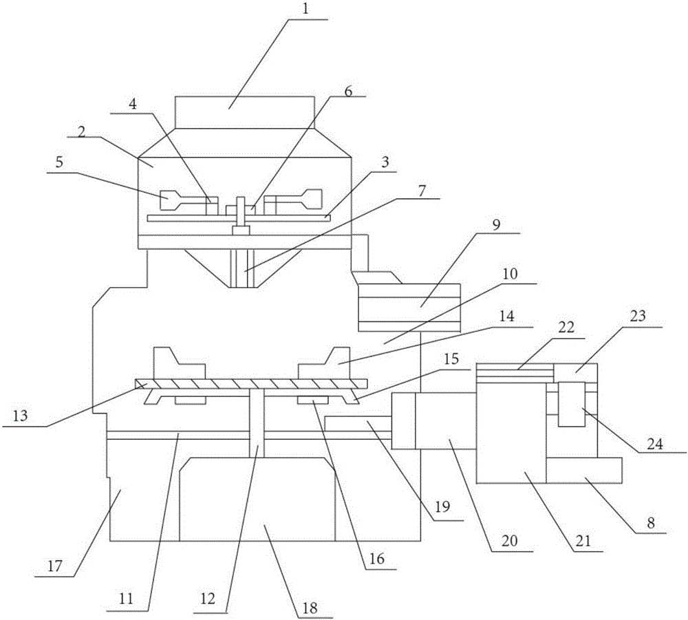
[0018] The specific implementation manners of the present invention will be briefly described below in conjunction with the accompanying drawings.

[0019] Such as figure 1 As shown, a food waste treatment device includes: a feed inlet 1, a first grinding chamber 2, a cutter head 3, a hinge shaft 4, a crushing block 5, a driving device 6, a discharge port 7, a second discharge Tube 8, protective cover 9, second grinding chamber 10, transverse partition 11, connecting shaft 12, grinding disc 13, rotary impact head 14, propulsion cutter head 15, guide block 16, motor chamber 17, drive motor 18, guide plate 19. The first discharge pipe 20, the microwave sterilization chamber 21, the heating pipe 22, the control device 23 and the microwave production device 24, the lower end of the feeding port 1 is provided with a first grinding chamber 2, and the inside of the first grinding chamber 2 is A cutterhead 3 is provided, and a driving device 6 is arranged on the upper end of the cutt...


PUM


Abstract

The invention discloses a kitchen waste treatment device. The kitchen waste treatment device comprises a feeding port, a first grinding cavity, a cutter head, hinge shafts, crushing beat blocks, a drive device, a discharging port, a second discharging pipe, a protection cover, a second grinding cavity, a transverse partition plate, a connecting rotary shaft, a grinding disc, rotation impact heads, a pushing cutter bit, guiding blocks, a motor cavity, a drive motor, a guiding plate, a first discharging pipe, a microwave sterilizing cavity, a heating pipe, a control device and a microwave generation device. The first grinding cavity is formed in the lower end of the feeding port. The cutter head is arranged in the first grinding cavity. The drive device is arranged at the upper end of the cutter head and fixedly connected with the cutter head. The crushing beat blocks are arranged on one side of the drive device and connected with the cutter head through the hinge shafts. The discharging port is formed in the lower end of the cutter head, and formed in the second grinding cavity. The kitchen waste treatment device has the beneficial effects that blockage is not likely to happen, safety and sterility are achieved, and cost is low.

Description

technical field [0001] The invention relates to the field of kitchen waste treatment, in particular to a kitchen waste treatment device. Background technique [0002] At present, general large cities produce more than 3,000 tons of domestic waste every day, of which kitchen waste accounts for about 50%. How to efficiently and quickly dispose of kitchen waste has always been a common concern of the government and society. Food waste will affect people's visual and olfactory comfort and living hygiene. High moisture content and organic components, and the difficulty of garbage transportation and disposal due to high moisture content. In addition, food waste can increase landfill gas production and leachate precipitation, which can contaminate surface and groundwater. As feed to feed livestock, food waste is eaten by pigs, and harmful substances accumulate in the fat, muscle and other tissues of pigs. After people eat such pork to a certain extent, it will lead to a decline ...

Claims


Application Information

Patent Timeline
Patent Type & Authority Applications(China)
IPC IPC(8): B02C18/12B02C13/14B02C21/00A61L2/12
CPCB02C18/12A61L2/12B02C13/14B02C21/00B02C2201/06
Inventor 孙浩
Owner 霍普科技(天津)股份有限公司
Why Eureka
Try Eureka