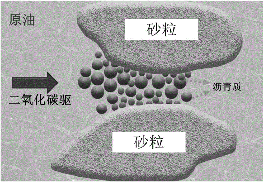
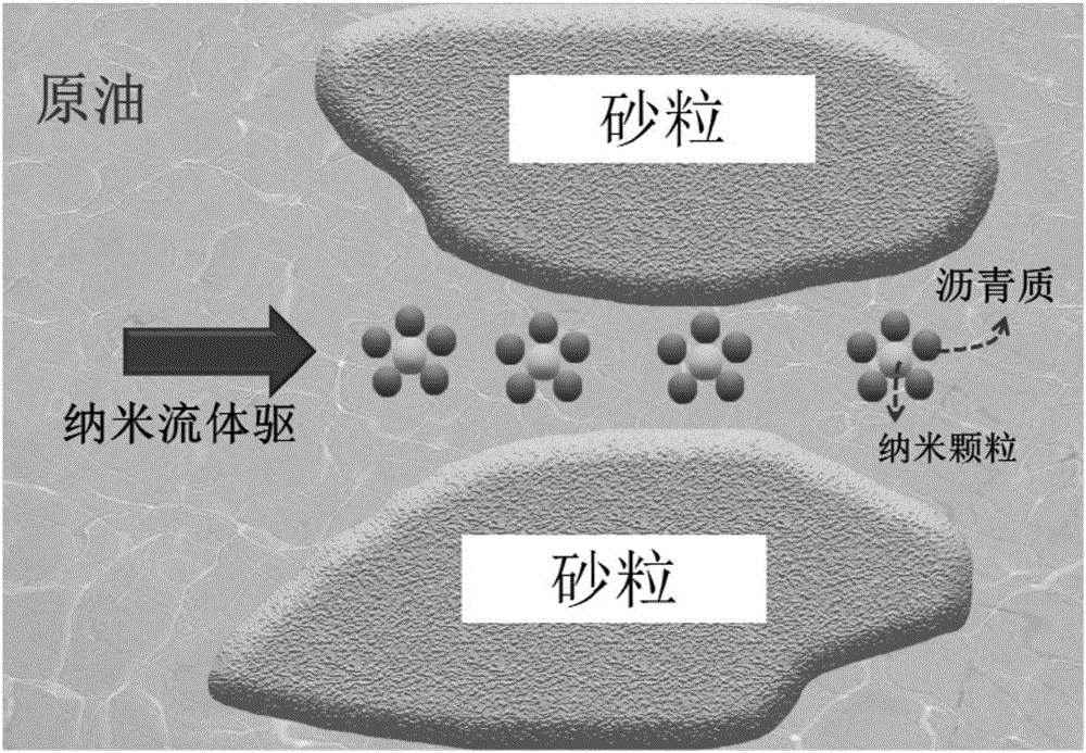
Method for inhibiting asphaltene deposition damage during hypotonic reservoir carbon dioxide flooding process through nanometer fluid
A nano-fluid, carbon dioxide technology, applied in chemical instruments and methods, fluid extraction, earthwork drilling, etc., can solve problems such as the inability to prevent asphaltene deposition, and achieve the effect of preventing reservoir damage and solving deposition problems.
- Summary
- Abstract
- Description
- Claims
- Application Information
AI Technical Summary
Problems solved by technology
Method used
Image
Examples
Embodiment 1
[0028] The low-permeability core is placed in the core holder, saturated water is injected first, and then saturated oil is injected to obtain a simulated low-permeability reservoir. First inject 2PV crude oil into the simulated low-permeability reservoir to test the core permeability k1, then inject carbon dioxide and nanofluid at the same time with a volume of 2PV, and finally re-inject 2PV crude oil to test the core permeability k2.
[0029] The low-permeability core has an inner diameter of 2.54 cm, a length of 5 cm, and a permeability of 8.5 mD. The composition of the nanofluid is: SiO with a particle size of 10nm-30nm 2 The mass fraction of nanoparticles is 0.5%, the mass fraction of anionic surfactant is 0.1%, and the balance is water. The anionic surfactant is sodium petroleum sulfonate, the injection volume of carbon dioxide is 2PV, the injection volume of nanofluid is 0.1PV, and the injection velocity of nanofluid is 0.5m / d.
Embodiment 2
[0031] As described in Example 1, the difference is:
[0032] The inner diameter of the low-permeability rock core is 2.54cm, the length is 5cm, and the permeability is 8.3mD. The composition of the nanofluid is: SiO with a particle size of 10nm-30nm 2 The mass fraction of nanoparticles is 0.05%, the mass fraction of anionic surfactant is 0.5%, and the balance is water. The anionic surfactant is petroleum sodium carboxylate, the injection volume of carbon dioxide is 2PV, the injection volume of nanofluid is 0.1PV, and the injection velocity of nanofluid is 0.8m / d.
Embodiment 3
[0034] The low-permeability core is placed in the core holder, saturated water is injected first, and then saturated oil is injected to obtain a simulated low-permeability reservoir. First inject 2PV crude oil into the simulated low-permeability reservoir to test the core permeability k1, then alternately inject carbon dioxide and nanofluid, first inject carbon dioxide with a volume of 2PV, and finally re-inject 2PV crude oil to test the core permeability k2.
[0035] The inner diameter of the low-permeability core is 2.54cm, the length is 5cm, and the permeability is 8.4mD. The composition of the nanofluid is: SiO with a particle size of 10nm-30nm 2 The mass fraction of nanoparticles is 0.1%, the mass fraction of anionic surfactant is 0.2%, and the balance is water. The anionic surfactant is sodium petroleum sulfonate, the injection volume of carbon dioxide is 2PV, the injection volume of nanofluid is 0.025PV, the volume ratio of carbon dioxide and nanofluid is 80:1, and the...
PUM
| Property | Measurement | Unit |
|---|---|---|
| particle diameter | aaaaa | aaaaa |
| diameter | aaaaa | aaaaa |
| viscosity | aaaaa | aaaaa |
Abstract
Description
Claims
Application Information
 - R&D
- Intellectual Property
- Life Sciences
- Materials
- Tech Scout
- Unparalleled Data Quality
- Higher Quality Content
- 60% Fewer Hallucinations
Browse by: Latest US Patents, China's latest patents, Technical Efficacy Thesaurus, Application Domain, Technology Topic, Popular Technical Reports.
© 2025 PatSnap. All rights reserved.Legal|Privacy policy|Modern Slavery Act Transparency Statement|Sitemap|About US| Contact US: help@patsnap.com


