Heat accumulating type pure air heating system with constant outlet temperature

A technology of outlet temperature and air heating, which is applied in heat storage heaters, fluid heaters, lighting and heating equipment, etc., and can solve problems such as unadjustable high-temperature air temperature

Active Publication Date: 2016-11-16
BEIHANG UNIV
6 Cites 4 Cited by

AI-Extracted Technical Summary

Problems solved by technology

[0007] The technical problem to be solved by the present invention is to provide a regenerative heating system capable of supplying high-temperature, high-pressure pure ...

Abstract

The invention discloses a heat accumulating type pure air heating system with the constant outlet temperature. The heat accumulating type pure air heating system comprises a heat accumulator, a burner and a pipeline heat exchanger. The heat accumulator is horizontally arranged, and a ceramic honeycomb body is mounted in the heat accumulator. The burner is mounted at the front end of the heat accumulator and connected with the heat accumulator through a flange. The pipeline heat exchanger is mounted at the rear end of the heat accumulator and connected with the heat accumulator through a flange. After heat accumulation is completed by the heat accumulator, normal-temperature high-pressure air is introduced through the front end of the heat accumulator, passes through the heat accumulator and then enters the pipeline heat exchanger, the temperature of the outlet high-pressure air is controlled to be the specified temperature by adjusting the water flow entering the pipeline heat exchanger at the moment, and the cooling water flow is gradually reduced along with time, so that the exhausted high-pressure air outlet temperature is kept constant as the specified temperature. The heat accumulating type pure air heating system is suitable for ground test systems needing high-temperature high-pressure pure air and can provide the high-temperature high-pressure pure air with the constant temperature for a long time.

Application Domain

Storage heatersStationary tubular conduit assemblies

Technology Topic

Heating systemEngineering +7

Image

  • Heat accumulating type pure air heating system with constant outlet temperature
  • Heat accumulating type pure air heating system with constant outlet temperature
  • Heat accumulating type pure air heating system with constant outlet temperature

Examples

  • Experimental program(1)

Example Embodiment

[0023] The present invention will be further described below with reference to the accompanying drawings and specific embodiments.
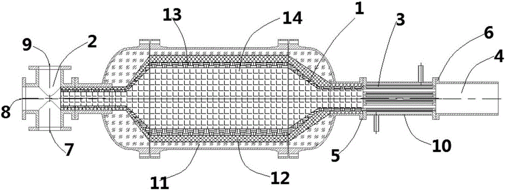
[0024] figure 1 It is a schematic diagram of the structure of the high temperature and high pressure pure air regenerative heating system with adjustable outlet temperature. The temperature range of high temperature and high pressure air is 600~1500K, and the pressure range is 1~3.5MPa.
[0025] The present invention includes a regenerator 1 , a burner 2 , a pipeline heat exchanger 3 , a high-pressure air inlet 7 , a liquefied petroleum gas inlet 8 , and a fan air inlet 9 . The burner 2 is installed at the front end of the regenerator 1, and the tail is connected to the front end of the regenerator 1. The burner 2 has three interfaces, which are the high-pressure air inlet 7, the liquefied petroleum gas inlet 8, and the fan air inlet 9; pipeline heat exchange The accumulator 3 is installed after the heat accumulator 1 and placed horizontally.
[0026] The whole working process of the system of the present invention: the preheating stage of the heat accumulator 1: the fan air and the liquefied petroleum gas are respectively supplied to the burner 2 through the fan air inlet 9 and the liquefied petroleum gas inlet 8 for mixed combustion, and the hot gas after combustion is passed through. Put the heat accumulator 1 into the heat accumulator 1 to preheat the heat accumulator 1. When the heat accumulator 1 is heated to the specified temperature, the liquefied petroleum gas inlet 8 stops the supply of liquefied petroleum gas, and the fan air inlet 9 continues to supply air for purging for 5 minutes. The residual gas in the regenerator 1 is purged clean; the heat release stage of the regenerator 1: the high-pressure air is introduced into the regenerator 1 from the high-pressure air inlet 7, and the process of flowing through the regenerator 1 is the process of being heated. When the outlet of regenerator 1 is heated to the specified temperature, the high-temperature and high-pressure air flowing out from the outlet of regenerator 1 enters the pipeline heat exchanger 3, and reaches the specified temperature through the heat exchange effect of the heat exchanger, and the purer high-temperature and high-pressure air passes through. The outlet pipe 4 is discharged.
[0027] figure 2 , image 3 It is a schematic diagram of the structure of the pipeline heat exchanger. The pipeline heat exchanger 3 is subjected to a pressure of 6MPa and a temperature of 1300K. The pipeline heat exchanger 3 includes the pipeline heat exchanger outlet pipe 18, the pipeline heat exchanger heat exchange pipe 17, the pipeline heat exchanger left flange 15, the pipeline heat exchanger right flange 19, the pipeline heat exchanger water inlet pipe 16, and the pipeline heat exchanger. Heat exchanger housing 10 . The left flange 15 of the pipeline heat exchanger is welded with the heat exchanger shell 10, the right flange 19 of the pipeline heat exchanger is welded with the heat exchanger shell 10, and the heat exchange tubes 17 of the pipeline heat exchanger are respectively connected with the left flange 15 of the pipeline heat exchanger. It is welded with the right flange 19 of the pipe heat exchanger, the water outlet pipe 18 of the pipe heat exchanger is welded with the casing 10 of the pipe heat exchanger, and the water inlet pipe 16 of the pipe heat exchanger is welded with the casing 10 of the pipe heat exchanger. The high-temperature and high-pressure air flowing out from the outlet of the heat accumulator 1 enters the pipeline heat exchanger 3, and the outlet temperature is adjusted through the adjustment of the water volume in the pipeline heat exchanger 3, and because the diameter of the heat exchanger conduit is small, it can be approximated that the gas temperature in the pipeline is approximated. consistent to obtain an isothermal gas.
[0028] In conclusion, the present invention is suitable for use in ground test systems requiring high-purity pure air with a constant outlet temperature.
[0029] Among them, the temperature range of high temperature and high pressure air is 600-1500K, and the pressure range is 1-3.5MPa; the pressure of the pipeline heat exchanger is 6MPa, and the temperature is 1500K; the diameter range of the heat exchange tube 21 of the pipeline heat exchanger is 6-18mm The diameter 20 of the outlet pipe of the pipe heat exchanger is 40-50mm; the length 22 of the pipe heat exchanger is 400-500mm; the diameter 23 of the pipe heat exchanger is 400-500mm.
[0030] The parts of the present invention that are not described in detail belong to the well-known technology in the art.
[0031] The above description is only a part of the specific embodiments of the present invention, but the protection scope of the present invention is not limited to this. Any person familiar with the art within the technical scope disclosed by the present invention can easily think of changes or substitutions. Included within the scope of protection of the present invention.

PUM

PropertyMeasurementUnit
Under pressure6.0MPa
Withstand temperature1500.0K
Length400.0 ~ 500.0mm

Description & Claims & Application Information

We can also present the details of the Description, Claims and Application information to help users get a comprehensive understanding of the technical details of the patent, such as background art, summary of invention, brief description of drawings, description of embodiments, and other original content. On the other hand, users can also determine the specific scope of protection of the technology through the list of claims; as well as understand the changes in the life cycle of the technology with the presentation of the patent timeline. Login to view more.
Why Eureka
Try Eureka