
Touch screen and touch display panel

A touch display panel and display panel technology, applied in the direction of instruments, electrical digital data processing, data processing input/output process, etc., can solve the problems of poor disappearing effect, easy peeling, affecting OGS touch function, etc.

Inactive Publication Date: 2016-11-16
BOE TECH GRP CO LTD +1
View PDF5 Cites 8 Cited by
  • Summary
  • Abstract
  • Description
  • Claims
  • Application Information

AI Technical Summary

Problems solved by technology

The basic schemes include: One scheme is to use two layers of different refractive index layer structures on the bottom layer of the substrate glass to achieve a small color difference between the sensor and the sensor, and to achieve a better customer appearance experience effect. This structure requires film The layer is thicker, and generally use intermediate frequency reactive sputtering to form a film, for O 2 The flow rate is very sensitive, and the refractive index of the film layer is unstable. When producing OGS products with a large size, in order to ensure the channel impedance, the film layer of the touch electrode of the sensor is required to be thicker, and the elimination effect is not good; another solution is, After the OGS functional film structure is completed, it is covered with a high-refractive-index film layer. The high-refractive-index film layer is made of silicon oxynitride material or high-refractive-index organic material. The film layer formed by the high-refractive-index organic material is not hard enough, and The thickness of the film formed by the silicon oxynitride material is thick and easy to peel off (peeling), and the single sensor cannot confirm the shadow removal effect, and the shadow removal effect can only be seen after bonding, which affects the OGS touch function and reduces the user experience effect

Method used


Image

  • Touch screen and touch display panel
  • Touch screen and touch display panel
  • Touch screen and touch display panel

Examples


Embodiment 1

[0031] This embodiment provides a touch screen, which has good anti-shadow effect and good appearance effect.

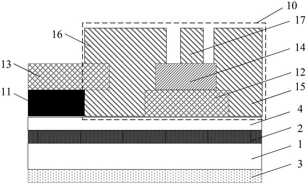
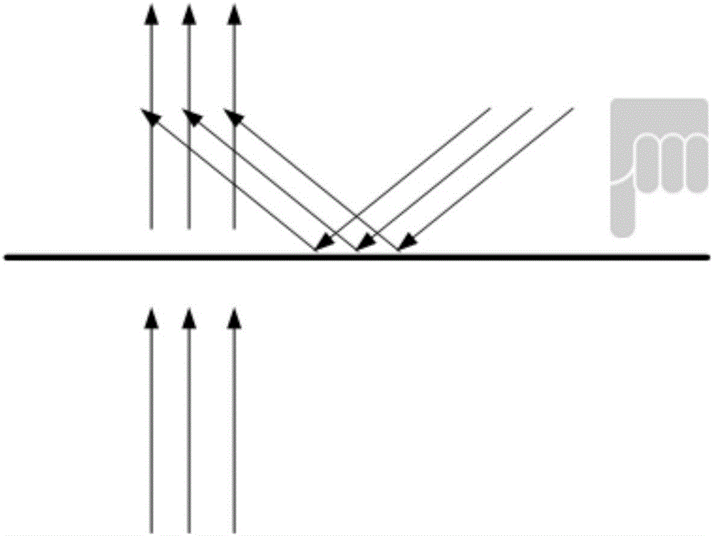
[0032] Such as figure 1 As shown, the touch screen includes a substrate 1 and a sensor 10 located above the substrate 1, and also includes a one-way light-transmitting film 2. The one-way light-transmitting film 2 is disposed between the substrate 1 and the sensor 10, and the one-way light-transmitting film 2 The light from the side of the sensor 10 is totally reflected, while the light from the side away from the sensor 10 is transmitted.

[0033] Among them, the unidirectional light-transmitting film 2 can be formed of a unidirectional light-transmitting insulating material or a unidirectional light-transmitting material with a higher transmittance, so that the external light from the touch side of the touch screen is fully The light from the inside of the display panel used in combination with the touch screen is transmitted, so as to achieve the effect that the touch ...

Embodiment 2

[0043] This embodiment provides a touch screen, which has good anti-shadow effect and good appearance effect. The difference from Embodiment 1 lies in the different setting positions of the unidirectional light-transmitting film 2.

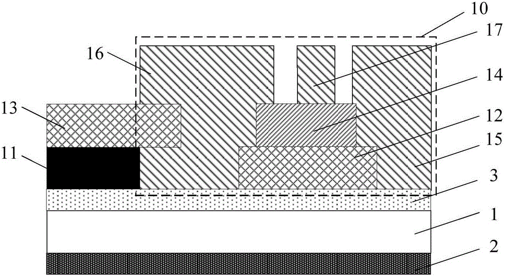
[0044] Such as image 3 As shown, the touch screen includes a substrate 1 and a sensor 10 located above the substrate 1, and also includes a one-way light-transmitting film 2. The one-way light-transmitting film 2 is arranged on the side of the substrate 1 away from the sensor 10, and the one-way light-transmitting film 2 makes the light from the side of the sensor 10 totally reflected, while the light from the side away from the sensor 10 is transmitted.

[0045] In the touch screen of this embodiment, a unidirectional light-transmitting film 2 is added on the other side of the substrate 1 where the sensor 10 is provided, and an anti-reflection layer 3 is provided on the side of the sensor 10. Since the anti-reflection layer 3 is insulating, it is Va...

Embodiment 3

[0050] This embodiment provides a touch display panel including the touch screen in Embodiment 1 or Embodiment 2.

[0051] Such as Figure 4 As shown, the touch display panel includes a display panel 5 and a touch screen. The touch screen is arranged on the display side of the display panel 5 and a flat layer 6 is arranged between the touch screen and the display panel 5. At present, the touch screen and the display panel 5 generally use optical clear resin (Optical Clear Resin, OCR) or optical clear adhesive (Optically Clear Adhesive, OCA) fully bonded products. At this time, optical clear resin and optical clear adhesive are Can serve as a flat layer 6.

[0052] Here, the display panel is a liquid crystal display (Liquid Crystal Display, abbreviated as LCD) or an organic light-emitting diode (Organic Light-Emitting Diode, abbreviated as OLED) display substrate.

[0053] Among them, considering the poor transmittance of the aluminum layer forming the unidirectional light-transmitt...


PUM

PropertyMeasurementUnit
Thicknessaaaaaaaaaa

Abstract

The invention belongs to the technical field of display and particularly relates to a touch screen and a touch display panel. The touch screen comprises a substrate and a sensor located above the substrate and further comprises a one-way light transmitting film, wherein the one-way light transmitting film is arranged between the substrate and the sensor or is arranged on the side, away from the sensor, of the substrate, so that the light from the side, close to the sensor, of the one-way light transmitting film is totally reflected, and the light is transmitted from the side, deviating from the sensor, of the one-way light transmitting film. The touch screen can decrease unstable factors in an existing OGS shadow-eliminating production process by adding one layer of one-way light transmitting film material, and the shadow-eliminating effect of invisible touch electrode patterns of an OG S sensor is achieved, or the light transmitting rate of the touch screen is ensured by further increasing one antireflection layer, the touch screen is simple in film layer structure, a preparation process is stable.

Description

Technical field [0001] The invention belongs to the field of display technology, and specifically relates to a touch screen and a touch display panel. Background technique [0002] OGS (One Glass Solution) touch screen is an electronic product protection screen that directly forms a conductive film and a sensor on the substrate glass. The substrate glass also plays a dual role of protecting the glass and the sensor. At present, in the production process of OGS, in order to achieve a better appearance effect, an anti-imaging layer is added to achieve the visual effect that the touch electrode pattern of the sensor is invisible. [0003] At present, the commonly used de-imaging method is Index Match ITO, which means that a transition film is coated on the sensor. Through the principle of light interference, the reflectivity of the conductive film layer and the non-conductive film layer is close , To achieve the effect that the human eye cannot distinguish. The basic plan includes: ...

Claims


Application Information

Patent Timeline
IPC IPC(8): G06F3/041G06F3/044
CPCG06F3/0412G06F3/044
Inventor 陈启程
Owner BOE TECH GRP CO LTD
Learn More