Transistor drive control method of push-pull converter and controller thereof

A drive controller and drive control technology, applied in control/regulation systems, DC power input conversion to DC power output, instruments, etc., can solve the problems that the capacitance cannot be set too large, the production efficiency is low, and the transformer production requirements are high.

Active Publication Date: 2016-11-16
MORNSUN GUANGZHOU SCI & TECH +1
View PDF11 Cites 14 Cited by
  • Summary
  • Abstract
  • Description
  • Claims
  • Application Information

AI Technical Summary

Problems solved by technology

However, in practical applications, this capacitor cannot be set too large, so the oscillation frequency generated during the startup process can only be controlled above 1MHz.
[0013] 2. The output with capacitive load capacity is poor and the reliability of the short circuit protection function is poor
However, since this method needs to adjust the leakage inductance of the transformer according to the actual situation, the requirements for the production of the transformer are relatively high. In the case of large-scale mass production, it will lead to problems such as low production efficiency and increased production costs.

Method used


Image

  • Transistor drive control method of push-pull converter and controller thereof
  • Transistor drive control method of push-pull converter and controller thereof
  • Transistor drive control method of push-pull converter and controller thereof

Examples


Embodiment 1

[0049] In order to make it easier for people to understand the transistor driving control method of the push-pull converter of the present invention, this embodiment uses a control flow chart to describe the control process in detail, as Figure 4 As shown, it is easy to see that there are 3 cyclic states, which are in different cyclic states under different working conditions:

[0050] When the converter is just started, the voltage of the output capacitor is zero, and the converter first enters the first cycle state, that is: start → select the current-limiting driving mode → determine the power tube driving mode as current-limiting driving → follow the current-limiting driving mode Drive the selected power tube → detect the conduction voltage drop of the power tube → determine that the voltage drop is greater than the set value → record that the number of overvoltages increases by 1 → the number of times does not exceed the set value → select the current limiting drive again...

Embodiment 2

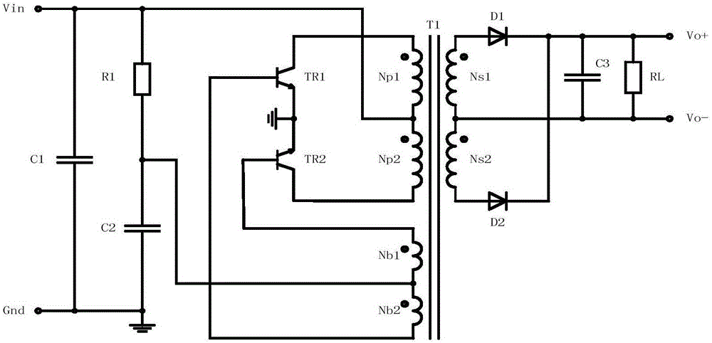
[0059] Such as Image 6 The part of the dashed box 200 shown is the transistor drive controller of the push-pull converter of the present invention. Compared with the first embodiment, the difference of this embodiment is that the driven power transistor is a triode. Because the triode is a current-driven device, the corresponding driving power supply module becomes a driving current module, which provides a small driving current in the current-limited working state, and it provides a large enough driving current in the fully driving state to make the triode The conduction voltage drop is small enough.


PUM


Abstract

The invention relates to a push-pull converter, especially to a transistor drive control method of a push-pull converter and a controller thereof. The transistor drive controller that is suitable for driving control of two push-pull transistors comprises a quasi complementary pulse width generator that generates two paths of quasi complementary time sequence signals; one path of time sequence signal controls a first transistor and the other path of time sequence signal controls a second transistor, thereby carrying out external excited push-pull drive control of the two push-pull transistors. Compared with the prior art, the provided method and the controller have the following beneficial effects: transistors are in full conduction in a normal working sate and the working efficiency of the push-pull converter is not affected. When starting begins and the output of the converter is in a short-circuit mode, the inductor effect is out of action because the primary winding of the transformer is clamped and large voltages are applied on the two ends of the transistors; and when the state is detected continuously, entrance to a protection state is realized. Therefore, burning under heavy currents and high voltages can be avoided.

Description

technical field [0001] The invention relates to a push-pull converter, in particular to a transistor driving control method of the push-pull converter and a controller thereof. Background technique [0002] The circuit structure of the push-pull converter is simple, the transformer is bidirectionally excited during operation, and the utilization rate of the magnetic core is high. Therefore, the converter has the advantages of small size, high efficiency and good dynamic response. It is widely used where electrical isolation is required. [0003] figure 1 The circuit shown is a common self-excited push-pull converter in the prior art, which adopts a ROYER circuit structure, and the input filter capacitor C1 is connected between the voltage input terminal Vin and the ground Gnd to filter the input voltage. The final input voltage is connected to the soft-start circuit composed of resistor R1 and capacitor C2. The resistor R1 and capacitor C2 are connected in series and then ...

Claims


Application Information

Patent Timeline
Patent Type & Authority Applications(China)
IPC IPC(8): H02M3/337
CPCH02M3/3376
Inventor 唐盛斌周耀彬余凤兵
Owner MORNSUN GUANGZHOU SCI & TECH
Why Eureka
Try Eureka