Ball grinding mill

A ball mill and ball mill barrel technology, applied in grain processing, gear lubrication/cooling, etc., can solve the problems affecting production, quality and operation rate, affecting the crushing efficiency of ball mills, limited centrifugal force lifting capacity, etc., achieving good sound absorption effect, extending equipment Service life, the effect of reducing energy consumption

Inactive Publication Date: 2016-11-23
苏州旋特自动化科技有限公司
View PDF0 Cites 11 Cited by
  • Summary
  • Abstract
  • Description
  • Claims
  • Application Information

AI Technical Summary

Problems solved by technology

After the ball mill has been working for a long time, it is necessary to add butter to the gears and other places for lubrication. Since the protective cover is not easy to be opened, the oil cup is mainly used to pour the butter from the small hole on the protective cover directly to the gear of the ball mill. However, due to the Poor fluidity, butter is not easy to be added to the gears in the ball mill, resulting in too little or no butter added to the gears, which is easy to cause rust and corrosion of the gears, long-term rusted gears will affect the crushing efficiency of the ball mill, and even the gears If it is damaged, it needs to be replaced with a new gear, which is time-consuming and labor-intensive
Existing ball mills generally use the centrifugal force during rotation to lift the steel ball inside, and crush the material through the interaction between the steel ball and the material. However, the lifting capacity of the centrifugal force is limited. Before the steel ball reaches the top, it will Falling due to gravity, unable to reach the maximum co-grinding speed. At the same time, due to the huge impact and friction of the steel ball on the ball mill cylinder, serious noise pollution is generated. The greater the speed of the steel ball, the greater the noise
Moreover, ball mills are prone to paste grinding under the combined action of water and static electricity. Without changing the working conditions, the paste grinding will become more and more serious with time, and may eventually have to be stopped and can only be restored after manual treatment. Seriously affect production, quality and operation rate, and the unit energy consumption will increase significantly

Method used


Image

  • Ball grinding mill
  • Ball grinding mill
  • Ball grinding mill

Examples


Embodiment Construction

[0013] The following will clearly and completely describe the technical solutions in the embodiments of the present invention with reference to the accompanying drawings in the embodiments of the present invention. Obviously, the described embodiments are only some, not all, embodiments of the present invention. Based on the embodiments of the present invention, all other embodiments obtained by persons of ordinary skill in the art without making creative efforts belong to the protection scope of the present invention.

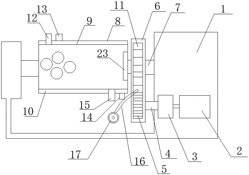
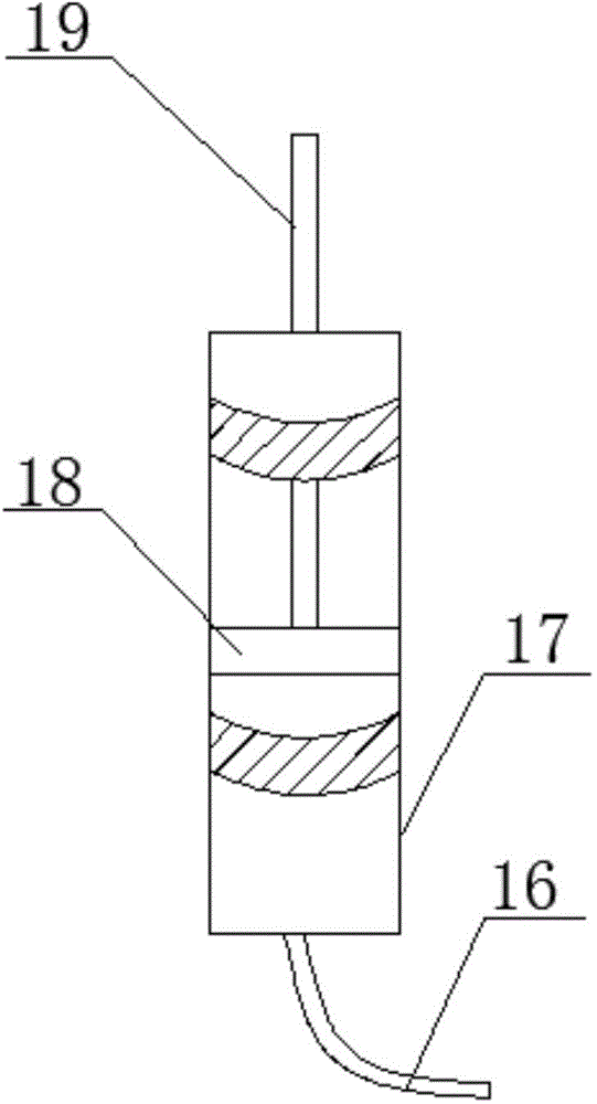
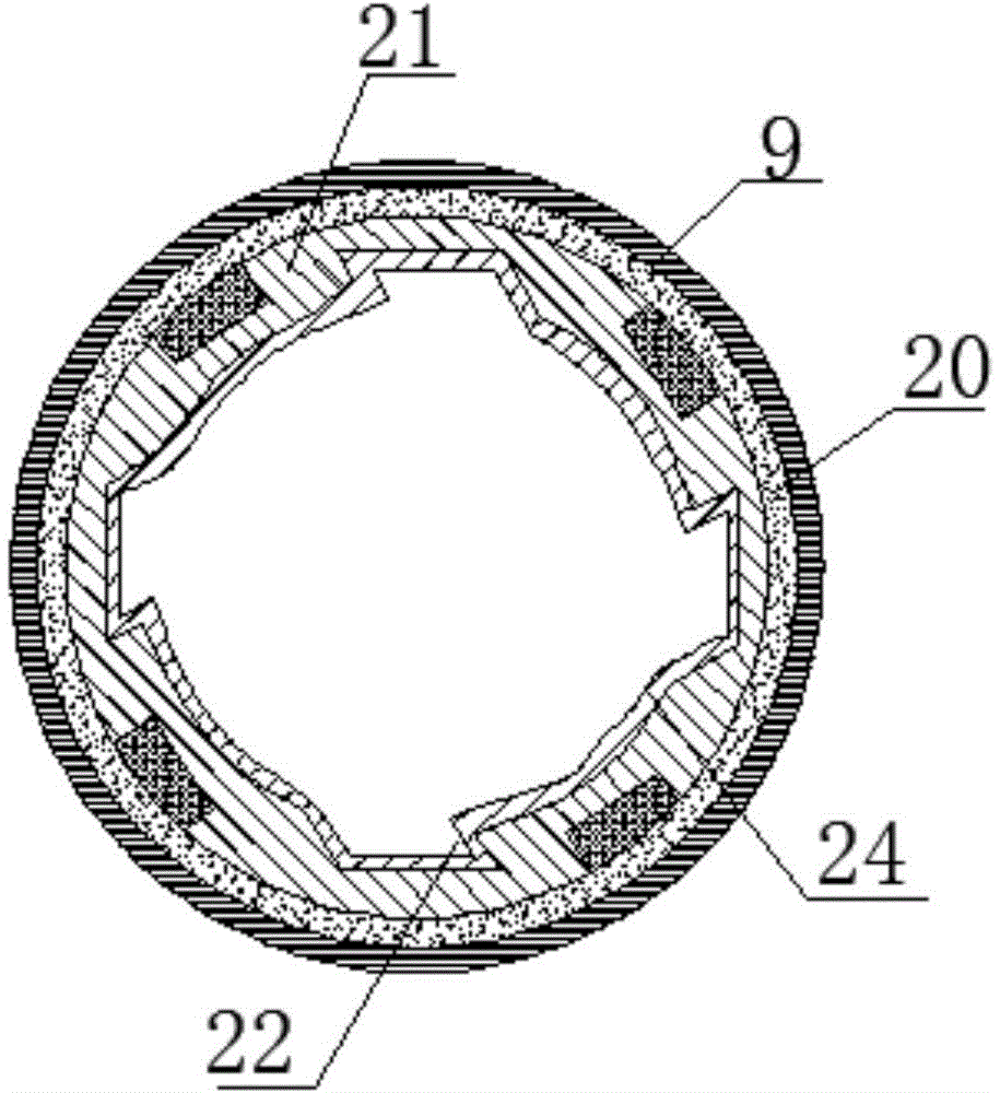
[0014] see Figure 1~3 , in an embodiment of the present invention, a ball mill includes a frame 1 and a ball mill cylinder, a motor 2 is installed on the lower part of the right end of the frame 1, and a speed reducer 3 is connected to the output end of the motor 2, and the speed reducer 3 The output end of the drive shaft 4 is connected with a transmission shaft 4, and a driving gear 5 is installed on the transmission shaft 4. The left and right ends of the ...


PUM


Abstract

The invention discloses a ball grinding mill. The ball grinding mill comprises a machine frame and a ball grinding barrel. A motor is installed on the lower portion of the right end of the machine frame. The output end of the motor is connected with a speed reducer. The output end of the speed reducer is connected with a transmission shaft. The transmission shaft is provided with a drive gear. The left end and the right end of the ball grinding barrel are connected to the machine frame through rotating shafts. The rotating shaft at the right end is provided with a gear, and a protection cover is arranged outside the gear and the drive gear. The protection cover is provided with a hose stretching into the protection cover. The other end of the hose is connected with a piston barrel. The ball grinding barrel comprises an inner barrel body and an outer barrel body. A cooling cavity is formed between the inner barrel body and the outer barrel body. The cooling cavity is provided with a cooling liquid inlet and a cooling liquid outlet. A sound absorption material lining layer is arranged on the inner side of the inner barrel body. A lining plate is arranged on the inner side of the sound absorption material lining layer. A lifting groove is formed in the inner wall of the lining plate. The lifting groove and the inner wall of the lining plate are both provided with wear-resisting layers. A static elimination device is further arranged at the right end of the inside of the inner barrel body. The ball grinding mill is simple in structure, convenient to use, capable of achieving sound insulation and abrasion resistance, high in stability and long in service life.

Description

technical field [0001] The invention relates to the field of ball milling devices, in particular to a ball mill. Background technique [0002] Ball mill is the key equipment for crushing materials after being crushed. It is widely used in cement, silicate products, new building materials, refractory materials, chemical fertilizers, ferrous and non-ferrous metal beneficiation, glass ceramics and other production industries. It can process various ores Dry or wet grinding with other grindable materials. After the ball mill has been working for a long time, it is necessary to add butter to the gears and other places for lubrication. Since the protective cover is not easy to be opened, the oil cup is mainly used to pour the butter from the small hole on the protective cover directly to the gear of the ball mill. However, due to the Poor fluidity, butter is not easy to be added to the gears in the ball mill, resulting in too little or no butter added to the gears, which is easy ...

Claims


Application Information

Patent Timeline
Patent Type & Authority Applications(China)
IPC IPC(8): B02C17/10B02C17/22B02C17/24F16H57/04
Inventor 梁昀翔
Owner 苏州旋特自动化科技有限公司
Why Eureka
Try Eureka