Cutting Tool Made By Additive Manufacturing

A technology of cutting tools and cutting edges, which is applied in the field of preparation and design of metal cutting tools, can solve expensive problems, achieve the effects of improving mechanical properties and wear resistance, increasing design flexibility, and saving manufacturing time and costs

Active Publication Date: 2016-11-23
KENNAMETAL INC
View PDF8 Cites 5 Cited by
  • Summary
  • Abstract
  • Description
  • Claims
  • Application Information

AI Technical Summary

Problems solved by technology

Cemented tungsten carbide is an expensive material

Method used


Image

  • Cutting Tool Made By Additive Manufacturing
  • Cutting Tool Made By Additive Manufacturing
  • Cutting Tool Made By Additive Manufacturing

Examples


Embodiment Construction

[0014] The embodiments described herein may be more readily understood by reference to the following Detailed Description and Examples, as well as the foregoing and following. However, the elements, devices, and methods described herein are not limited to the specific embodiments described in the Detailed Description and Examples. It should be realized that these Examples are illustrative only of the principles of the invention. Various modifications and alterations will be apparent to those skilled in the art without departing from the spirit and scope of the invention. As used herein, the term cutting tool refers to a hard component used to remove material from a workpiece.

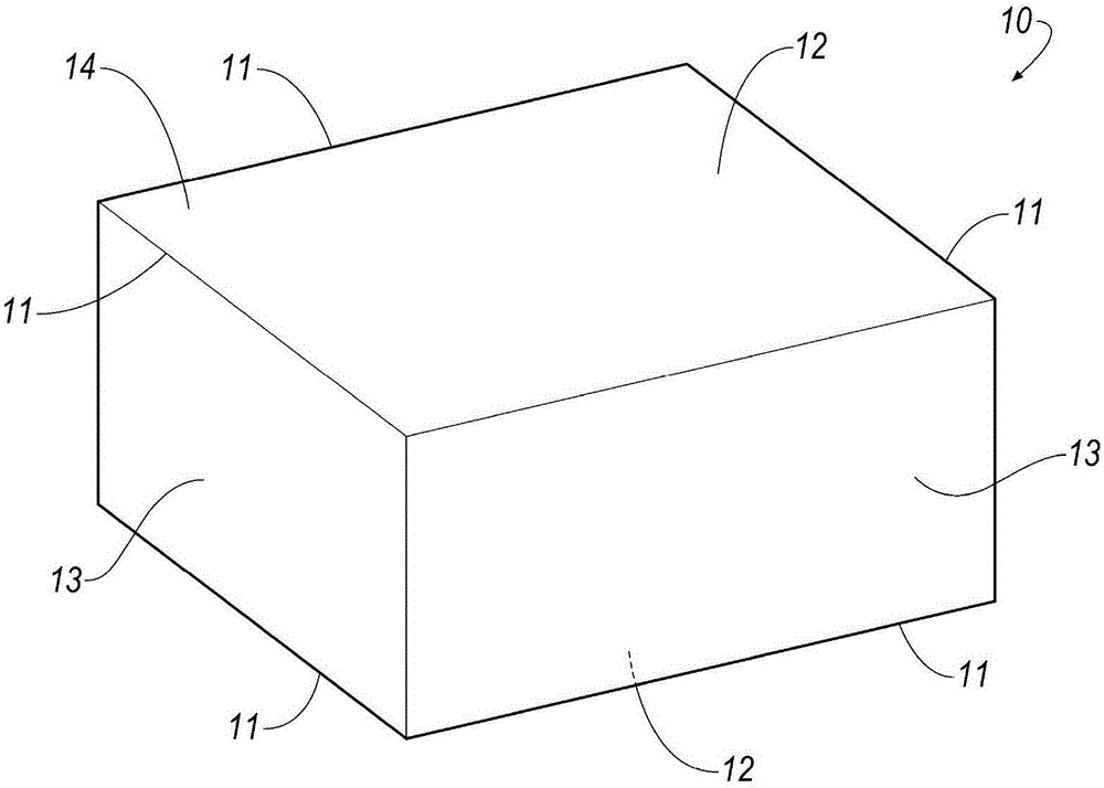
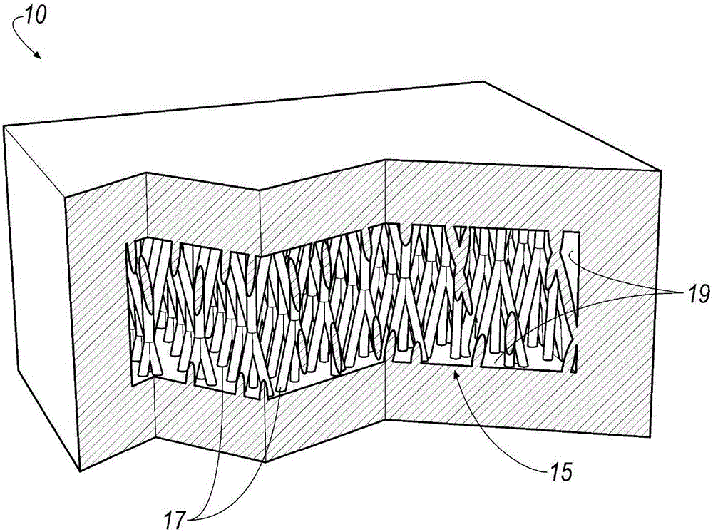
[0015] figure 1 A cutting insert 10 according to one embodiment of the invention is shown. In this embodiment, the cutting insert has a generally rectangular form, but the cutting insert may be of any desired shape suitable for metal cutting, such as another insert type, an end mill or a drill. Furt...


PUM


Abstract

A cutting tool made by an additive manufacturing process is disclosed. The cutting tool has an exterior surface and an enclosed interior cavity defined by one or more inwardly facing surfaces. The interior cavity may have internal supports such as a lattice or a honeycomb structure. The cutting tool may be an insert, drill or endmill with coolant holes.

Description

technical field [0001] The present invention relates to the preparation and design of metal cutting tools. Background technique [0002] Metal cutting tools are usually made of cemented tungsten carbide or another suitable material such as PCD, PcBN, high speed steel and other cermets. Cemented tungsten carbide parts are made by pressing or extruding a blend of WC, Co, and possibly other materials into a green compact shape. The green shape is then sintered to compact and fuse the powders together. Cemented carbides are metal matrix composites comprising carbides of one or more transition metals dispersed as hard particles and cemented ) in the binder. In this way, the hard particles form the dispersed phase and the binder forms the continuous phase. For use as cutting tools including, for example, turning inserts and milling inserts, cemented carbides offer an attractive combination of strength, toughness, and wear / corrosion resistance (ie, wear resistance). Among the ...

Claims


Application Information

Patent Timeline
Patent Type & Authority Applications(China)
IPC IPC(8): B22F3/105B22F3/22B33Y10/00B33Y80/00
CPCB33Y10/00B33Y80/00B22F3/225B22F10/00B22F10/66B22F10/64B22F2998/10B22F10/14B22F9/08B22F2009/0828C22C1/051B22F10/28B22F3/15B23B27/10B23C2228/25B23B51/02B23B2222/28B23B2228/10B23B27/14C22C29/08B22F2005/001Y02P10/25B23C5/20B22F2999/00B22F5/10C22C29/067B22F2302/10B22F2301/15
Inventor P.斯托亚诺夫
Owner KENNAMETAL INC
Why Eureka
Try Eureka