Welding machine laser beam optical mode detection system and method

A detection system and laser beam technology, applied in laser welding equipment, welding equipment, metal processing equipment, etc., can solve problems such as wasting time and affecting production, and achieve the effect of improving efficiency, improving production efficiency, and shortening maintenance time

Active Publication Date: 2018-03-30
BAOSHAN IRON & STEEL CO LTD
View PDF6 Cites 0 Cited by
  • Summary
  • Abstract
  • Description
  • Claims
  • Application Information

AI Technical Summary

Problems solved by technology

[0003] The technical problem to be solved by the present invention is to provide a welding machine laser beam optical mode detection system and method, which solves the defects in the prior art that the detection needs to disassemble the laser source resonator, affects production and wastes time, and realizes the welding machine laser beam. The real-time detection of beam optical mode in the production process, and the online detection data can be used as an important indicator for the judgment of weld quality in the production process, which is conducive to improving the accuracy of weld quality judgment

Method used


Image

  • Welding machine laser beam optical mode detection system and method

Examples


Embodiment 1

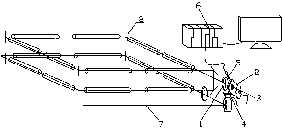
[0023] like figure 1 As shown, a welding machine laser beam optical mode detection system includes a laser power measuring head 2 arranged on the back of the laser output back mirror 1 of the laser output unit, and the photosensitive surface of the laser power measuring head 2 is coated with a layer of photosensitive A developing coating 3, an ultraviolet projection lamp 4 and a camera 5 are arranged near the laser power measuring head 2, the irradiation direction of the ultraviolet projection lamp 4 points to the photosensitive surface, and the shooting direction of the camera 5 points to the photosensitive surface, and the camera 5 passes data The picture on the photosensitive surface is transmitted to the external device through the line;

[0024] When testing the quality of the online optical mode, first start the laser output unit, at this time the laser output back mirror 1 in the laser output unit 8 will reflect 99.97% of the laser rays, and the remaining 0.03% of the l...


PUM

PropertyMeasurementUnit
wavelengthaaaaaaaaaa
thicknessaaaaaaaaaa
hardnessaaaaaaaaaa

Abstract

The invention relates to the field of laser welding of plate and strip steel, in particular to a laser calibration device and method for welding. A welding machine laser beam optical mode detection system, including a photosensitive developing coating coated on the photosensitive surface of a laser power measuring head; an ultraviolet projection lamp and a camera are also arranged near the laser power measuring head, and the irradiation direction of the ultraviolet projection lamp points to the photosensitive The shooting direction of the camera points to the photosensitive surface. A method for detecting the laser beam optical mode of a welding machine. A standard laser is selected, the standard laser is turned on, and the standard laser mode pattern is obtained from the photosensitive surface; the laser output unit to be detected is opened to obtain the laser mode pattern to be detected; the laser pattern pattern to be detected is obtained The deviation of the laser to be detected is obtained by comparing with the standard laser mode graph. The invention realizes the real-time detection of the laser beam optical mode of the butt welding machine in the production process, is beneficial to improving the accuracy of weld quality judgment, greatly shortens the required inspection and maintenance time, and improves the production efficiency.

Description

technical field [0001] The invention relates to the field of laser welding of plate and strip steel, in particular to a laser calibration device for welding. Background technique [0002] Cold-rolled acid continuous rolling laser welding machine is mainly used for welding hot-rolled strip steel with a thickness of 2mm-5mm and a hardness of HR30Te between 42-95. During the laser welding process, the operation and maintenance personnel can visually observe the color emitted by the laser during the laser welding process. To judge the state of the laser beam, this method of visually judging the color of the beam is particularly dependent on the experience of daily observation. It is a completely qualitative judgment, and there are great uncertainties and deviations. Carry out detection, identification and judgment; if detection is required, production must be stopped, the laser source resonant cavity is opened, the laser power measurement head is removed, a laser development boa...

Claims


Application Information

Patent Timeline
Patent Type & Authority Patents(China)
IPC IPC(8): B23K26/70
Inventor 陈杰王康健柯重建
Owner BAOSHAN IRON & STEEL CO LTD
Why Eureka
Try Eureka