
Shaft-mounted brake disc
A brake disc and shaft mounting technology, applied in the direction of brake discs, brake types, brake components, etc., can solve problems affecting product use and driving safety, difficulty in process realization, and increased stress sources on the disc surface. Sand cleaning and shot blasting operations, improving structural strength and crack resistance, and easy operation and installation
Patent Information
- Authority / Receiving Office
- CN · China
- Patent Type
- Applications(China)
- Current Assignee / Owner
- Publication Date
- 2016-11-23
Smart Images
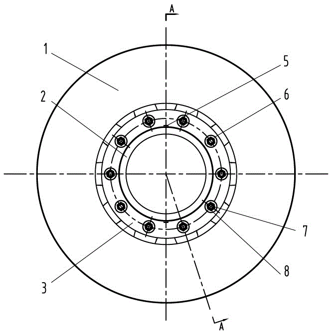
Figure 1 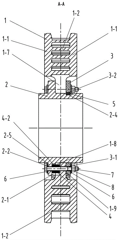
Figure 2 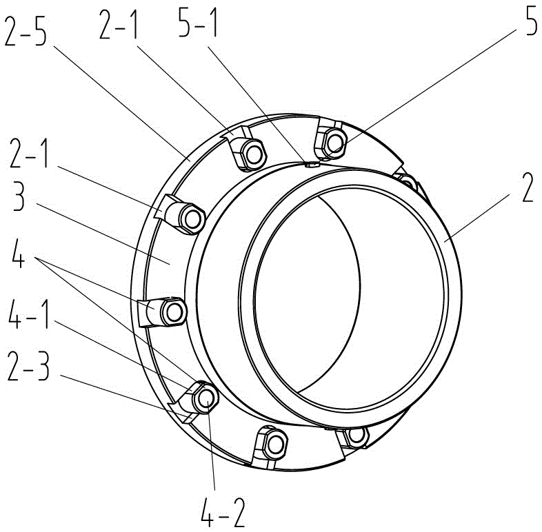
Figure 3
Abstract
Description
technical field
[0001] The invention relates to a rail transit vehicle brake device, in particular to a brake disc. Background technique
[0002] With the rapid development of rail transit, disc brakes are more and more used in the basic braking of rail transit vehicles because of their advantages such as stable friction performance, large energy absorption, good heat dissipation performance and little damage to the tread compared with tread brakes. device.
[0003] As an important part of the disc-shaped foundation braking device, the brake disc plays an important role in the braking process of the vehicle.
[0004] During the braking process of the vehicle, when the basic braking device is applied, the brake caliper moves and pushes the brake pad to act on the brake disc. Through the friction between the brake disc and the brake pad, the kinetic energy of the vehicle is converted into frictional heat energy and released. Thereby achieving vehicle braking.
[0005] Durin...
Examples
Embodiment Construction
[0029] Such as figure 1 , 2, 3, and 4, the shaft-mounted brake disc of the present invention includes a disc body 1, a hub 2, a spacer ring 3, a slider 4, a positioning key 5, a gasket 6, a bolt 7 and a nut 8, and the disc body 1 includes two friction rings 1-1, a plurality of heat dissipation ribs 1-2 connected between the two friction rings 1-1, and several connecting claws 1 located on the inner ring of the friction ring 1-1 and arranged along the circumferential direction -7, the plurality of cooling ribs 1-2 are arranged in multiple circles from inside to outside along the radial direction of the friction ring 1-1, wherein the cross-sectional area of the cooling ribs 1-2 of the inner ring is smaller than that of the adjacent outer ring The cross-sectional area of the heat dissipation rib 1-2, the cross-sectional center of the single heat dissipation rib 1-2 of the inner ring is located on the radial symmetry line between the two heat dissipation ribs 1-2 of the outer...