Magnetic sensitivity temperature compensation circuit and programmable linear Hall sensor chip

A temperature compensation circuit and sensitivity technology, applied in the direction of converting sensor output, using electromagnetic/magnetic devices to transmit sensing components, instruments, etc., can solve problems such as sensitivity reduction and output signal amplitude reduction, and achieve the effect of increasing sensitivity

Active Publication Date: 2016-11-23
CROSSCHIP MICROSYST
View PDF7 Cites 9 Cited by
  • Summary
  • Abstract
  • Description
  • Claims
  • Application Information

AI Technical Summary

Problems solved by technology

When the temperature rises, the resistance of the Hall sheet increases, the bias current I decreases,

Method used


Image

  • Magnetic sensitivity temperature compensation circuit and programmable linear Hall sensor chip
  • Magnetic sensitivity temperature compensation circuit and programmable linear Hall sensor chip
  • Magnetic sensitivity temperature compensation circuit and programmable linear Hall sensor chip

Examples


Example Embodiment

[0026] Example 1:

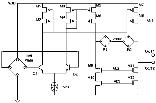
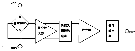
[0027] Such as Figure 1-3 As shown, the present invention includes a magnetic sensitivity temperature compensation circuit including Hall Plate and a differential amplifier. The Hall plate induces a magnetic field signal and converts it into a Hall voltage signal and outputs it to the input end of the differential amplifier. The difference is that the differential amplifier is a differential amplifier with adjustable gain, the tail current source Ibias on the differential amplifier is proportional to the absolute temperature, and the load resistances R1 and R2 on the differential amplifier are all of the same shape and material as the Hall sheet. .

[0028] Such as figure 1 As shown in the circuit, the differential amplifier includes op amp input NPN transistor pairs Q1 and Q2, a tail current source Ibias, a current mirror used to provide the gain amplification factor of the differential amplifier, and a series connection load resistor R1 and R2. The current ...

Example Embodiment

[0039] Example 2:

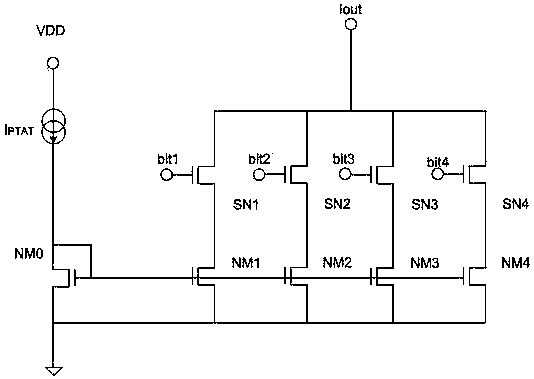
[0040] This embodiment is preferably as follows on the basis of Embodiment 1: The tail current source Ibias is a tail current source Ibias that can be programmed to control the amplification factor of the Hall voltage.

[0041] Such as image 3 As shown, it is an implementation of the tail current source Ibias. There are other different implementations of the tail current source Ibias. This example is a 4bit programming accuracy. The actual accuracy can be adjusted according to specific application needs. The tail current source Ibias includes a current source IPTAT proportional to the absolute temperature and an NMOS current mirror NM0. One end of the current source IPTAT is connected to the source of the NMOS current mirror NM0, the other end of the current source IPTAT is connected to the power supply VDD, and the drain of the NMOS current mirror is grounded. NM0 mirrors the current source IPTAT to the transistors NM1 to NM4, the NMOS transistors SN1 to SN4 s...

Example Embodiment

[0043] Example 3:

[0044] Based on the above-mentioned embodiment, this embodiment is preferably as follows: the voltage of the common node of the load resistors R1 and R2 is maintained at 1 / 2 of the power supply voltage through a voltage follower output. Only when the voltage of the common node is kept at this value, can the output signal swing of the linear Hall sensor chip be better guaranteed.


PUM


Abstract

The invention discloses a magnetic sensitivity temperature compensation circuit and a programmable linear Hall sensor chip. The magnetic sensitivity temperature compensation circuit comprises a Hall sheet and a differential amplifier, the Hall sheet senses a magnetic field signal, converts the magnetic field signal into a Hall voltage signal and outputs the Hall voltage signal to an input end of the differential amplifier, the magnetic sensitivity temperature compensation circuit further comprises a chopped wave offset cancellation circuit and an amplifier connected to output ends OUT1 and OUT2 of the differential amplifier, the amplifier is connected onto a signal output end of the chopped wave offset cancellation circuit, the Hall voltage signal amplified by the amplifier is outputted through an output port OUT on a buffer output stage, the differential amplifier is a gain adjustable differential amplifier, a tail current source Ibias of the differential amplifier is in direct proportion to the absolute temperature, and load resistors R1 and R2 on the differential amplifier both use load resistors in the same shape and material with the Hall sheet. Through the principle, the sensitivity of the Hall sheet is subjected to temperature compensation, so that the sensitivity of the chip is guaranteed not to change with the temperature.

Description

technical field [0001] The invention relates to the field of Hall sensors, in particular to a magnetic sensitivity temperature compensation circuit and a programmable linear Hall sensor chip. Background technique [0002] Pass a bias current I across both ends of the Hall sheet, and apply a magnetic field with a magnetic induction intensity B in the vertical direction of the sheet, then a potential difference will be generated in the direction perpendicular to the current and magnetic field, which is called the Hall voltage. V Hall [0003] V H a l l = k I B d [0004] I is the bias current flowing through the Hall sheet; [0005] B is the magnetic field size of the vertical Hall sheet; [0006] d is the thickness of the Hall sheet; [0007] k is the Hall coefficient, which is relat...

Claims


Application Information

Patent Timeline
IPC IPC(8): G01D5/14
CPCG01D5/142
Inventor 彭卓陈忠志赵翔
Owner CROSSCHIP MICROSYST
Why Eureka
Try Eureka