Circuit control method and device

A circuit control and circuit technology, applied in the field of circuit control methods and equipment, can solve the problems of soaring bus voltage and poor circuit performance

Active Publication Date: 2016-11-23
VERTIV CORP
View PDF5 Cites 2 Cited by
  • Summary
  • Abstract
  • Description
  • Claims
  • Application Information

AI Technical Summary

Problems solved by technology

[0006] The embodiment of the present invention provides a circuit control method and equipment to solve the current problem that when the BOOST PFC circuit works in discontinuous mode and the load is less than the set...

Method used


Image

  • Circuit control method and device
  • Circuit control method and device
  • Circuit control method and device

Examples


Embodiment 1

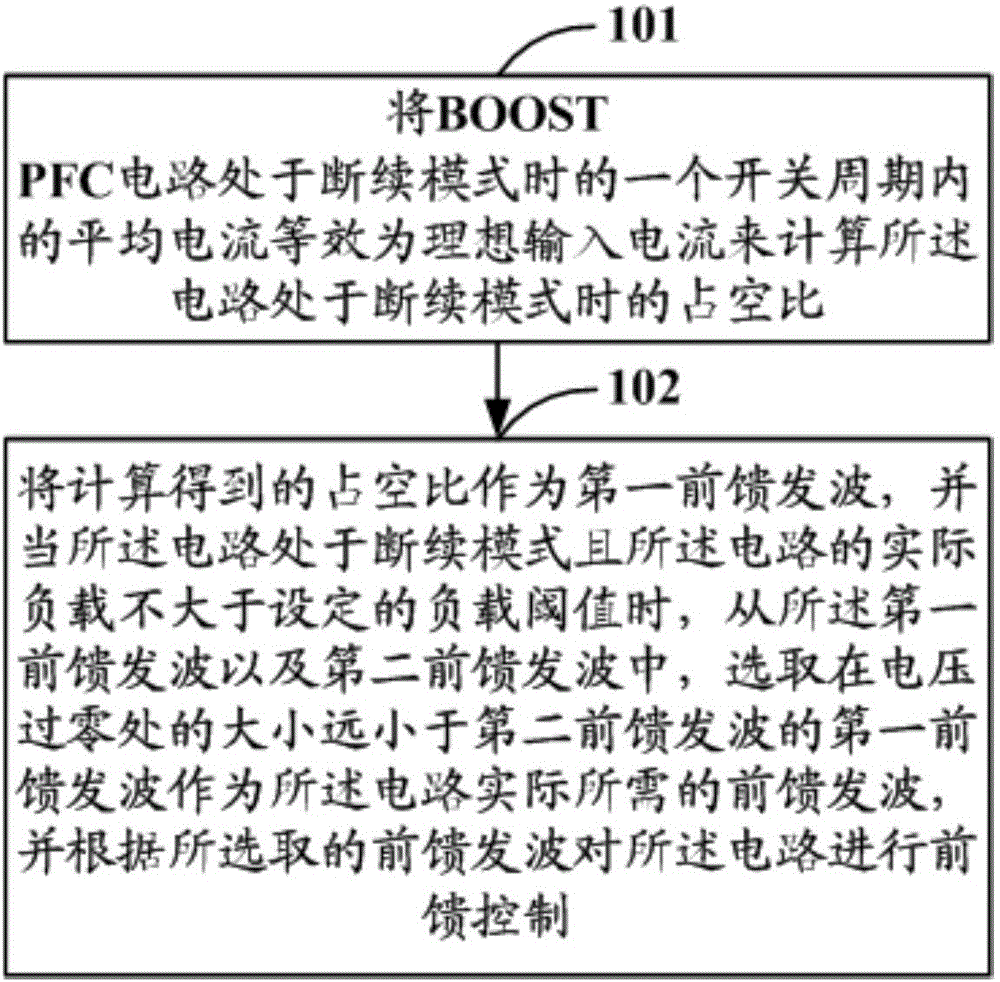
[0024] Embodiment 1 of the present invention provides a circuit control method applicable to BOOST PFC circuits, such as figure 1 As shown, it is a schematic flowchart of the circuit control method in Embodiment 1 of the present invention, and the circuit control method may include the following steps:

[0025] Step 101: Calculate the duty ratio when the BOOST PFC circuit is in the discontinuous mode by equating the average current in one switching cycle when the BOOST PFC circuit is in the discontinuous mode to an ideal input current.

[0026] Specifically, that the BOOST PFC circuit is in the discontinuous mode means that the inductor current of the BOOST PFC circuit works in the discontinuous mode, which will not be described in detail in this embodiment of the present invention.

[0027] Step 102: Use the calculated duty cycle as the first feed-forward transmission, and when the circuit is in the discontinuous mode and the actual load of the circuit is not greater than the...

Embodiment 2

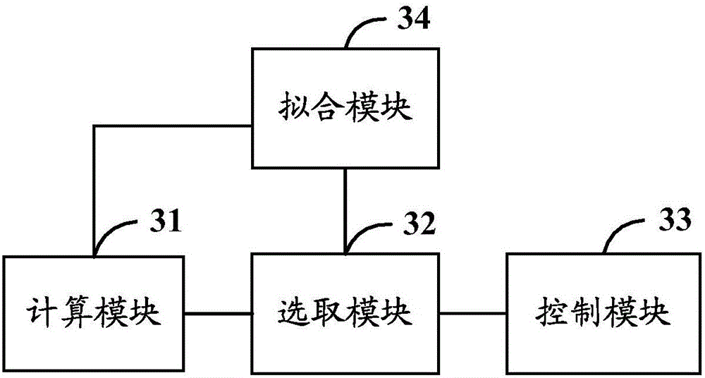
[0054] Based on the same inventive concept, Embodiment 2 of the present invention provides a circuit control device. For the specific implementation of the circuit control device, please refer to the relevant description in Embodiment 1 of the above-mentioned method. image 3 As shown, it is a schematic structural diagram of the circuit control device described in Embodiment 2 of the present invention, and the circuit control device may mainly include:

[0055] The calculation module 31 can be used to calculate the duty cycle when the BOOST PFC circuit is in the discontinuous mode by equating the average current in one switching cycle when the BOOST PFC circuit is in the discontinuous mode to an ideal input current;

[0056] The selection module 32 can be used to use the duty ratio calculated by the calculation module 31 as the first feed-forward transmission, and when it is determined that the circuit is in the discontinuous mode and the actual load of the circuit is not great...


PUM


Abstract

The invention discloses a circuit control method and device. The method includes the steps that the duty ratio of a boost power factor correction circuit in an intermittent mode is calculated with average current equivalence of the boost power factor correction circuit in the intermittent mode in a switching period as ideal input current; the duty ratio serves as a first feed-forward wave; when the circuit is in the intermittent mode and an actual load is not larger than a set load threshold, the first feed-forward wave with the amplitude at the voltage zero-crossing position much smaller than that of a second feed-forward wave is selected as a feed-forward wave of the circuit, feed-forward control is conducted on the circuit according to the selected feed-forward wave, wherein the second feed-forward wave is 1-Uin/UBus, so when the boost power factor correction circuit is in the intermittent mode and the load is small, the feed-forward wave of the circuit is much smaller than 1 at the voltage zero-crossing position, that is, the duty ratio is not full, the voltage of a bus cannot be increased, and the effects of improving the sinusoidal property of current, reducing the input current harmonic content, improving PF and the like can be achieved.

Description

technical field [0001] The invention relates to the technical field of circuit control, in particular to a circuit control method and equipment. Background technique [0002] When the BOOST PFC (boost power factor correction) circuit load is less than the set load threshold (such as small load or no load) and the inductor current works in discontinuous mode, if the traditional double-loop control + feedforward is still used to control the circuit accordingly Control, there will be a problem that the bus voltage soars when the voltage crosses zero. [0003] This is because the traditional double-loop control + feedforward uses the traditional feedforward wave 1-U suitable for continuous mode in / U Bus , where U in is the input voltage of the circuit, U Bus As a result, when the inductor current works in discontinuous mode, a large duty cycle will be generated at the point where the voltage crosses zero, so that the circuit will always charge the bus capacitor. If so When...

Claims


Application Information

Patent Timeline
IPC IPC(8): H02M1/42
CPCY02B70/10
Inventor 周扬姚少雄
Owner VERTIV CORP
Why Eureka
Try Eureka