
Clamping device for gas inflation type discharge capillary

A clamping device and capillary technology, applied in the direction of electrical components, accelerators, etc., can solve the problems of unstable discharge, short service life, and long time consumption, and achieve easy implementation, good clamping stability, and capillary replacement convenient effect

Active Publication Date: 2016-11-23
SHANGHAI INST OF OPTICS & FINE MECHANICS CHINESE ACAD OF SCI
View PDF5 Cites 5 Cited by
  • Summary
  • Abstract
  • Description
  • Claims
  • Application Information

AI Technical Summary

Problems solved by technology

[0003] At present, the gas-filled part of the gas-filled discharge capillary is formed by directly punching holes on the side of the capillary [see Document 1: C.Ciocarlan, S.M.Wiggins, et al. The role of the gas / plasma plume and self-focusing in a gas- filled capillary discharge waveguide for high-powerlaser-plasma applications.Physics of Plasmas 20,093108(2013).], but this side perforated capillary device is only suitable for some materials with good ductility, such as plexiglass, while ductility Good materials are used for discharge, their service life is relatively short, and the discharge is not very stable
If you use a material with high hardness, such as quartz glass, to make a capillary tube, although the service life is long and the discharge is stable, it will take a long time to complete the project on the side of this high-hardness capillary tube, and it will be punched out. It is difficult to make the hole thin and straight with smooth inner wall

Method used


Image

  • Clamping device for gas inflation type discharge capillary
  • Clamping device for gas inflation type discharge capillary

Examples


Embodiment Construction

[0030] The present invention will be further described below in conjunction with the embodiments and accompanying drawings, but the protection scope of the present invention should not be limited thereby.

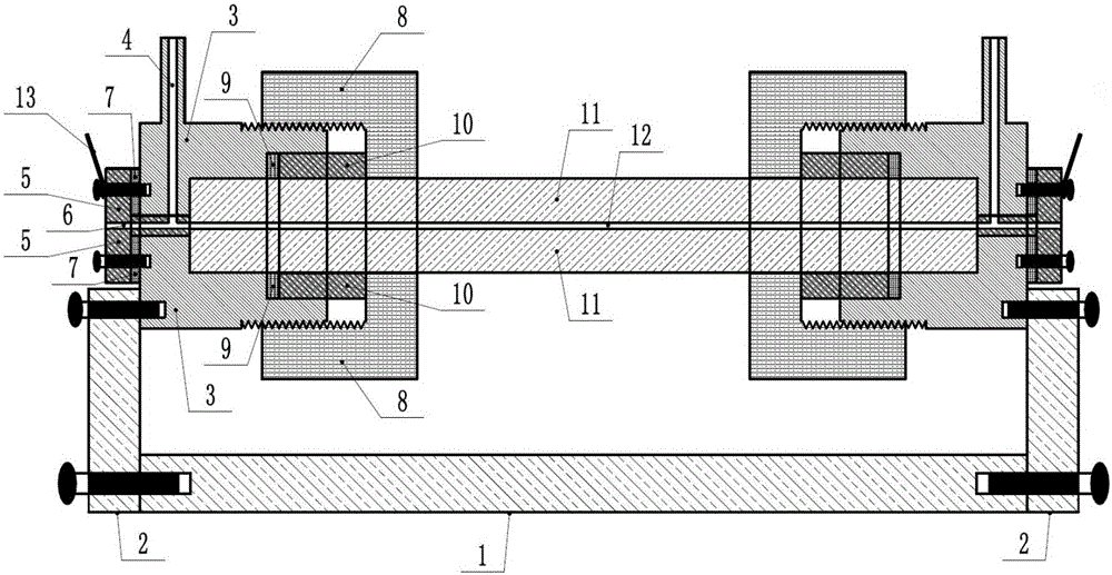
[0031] Such as figure 1 , figure 1 It is a schematic diagram of a clamping device for an inflatable discharge capillary based on the present invention. It can be seen from the figure that the device of the present invention includes: a support base 1, two support frames 2, a clamping sleeve 3, a T-shaped copper electrode 5, a sealing sleeve 8 and an extrusion sleeve 9, and the two support frames 2 are symmetrical fixed on the left and right ends of the support base, the clamping sleeve 3 is fixed on the support frame 2, the copper electrode 5 is embedded on the outside of the clamping sleeve 3, and the center of the copper electrode 5 is provided with an inverted T-shaped There is also a rubber pad 7 between the copper electrode 5 and the clamping sleeve 3, and the rubber...


PUM


Abstract

The invention discloses a clamping device for a gas inflation type discharge capillary. The clamping device comprises a support base, a support frame, a copper electrode, a clamping sleeve, a seal ring, an extrusion pipe sleeve, a seal pipe sleeve, a threaded steel sleeve, a wire, a rubber pad and screws. The clamping device has the characteristics of simple and compact structure, convenience in operation, good clamping stability, stable gas inflation and discharge, and excellent airtightness, the clamping device can be used repeatedly, and the capillary is changed conveniently. The clamping device is applied to the field of interaction of laser plasma on the basis of the gas inflation type discharge capillary, and particularly applied to acceleration of electrons in a laser wake-field.

Description

technical field [0001] The invention relates to a clamping device for an inflatable discharge capillary, which can be used in the field of laser plasma interaction, especially for accelerating electrons in a laser wake field. Background technique [0002] With the further increase of laser power, the development of electrons accelerated by the laser wakefield is getting faster and faster, and the energy requirements of electrons are getting higher and higher. For an acceleration gradient of 100Gev / m, if you want to accelerate to 10Gev energy, you need an acceleration length of at least 10cm. If you want the laser to maintain a high acceleration gradient over such a long distance, the laser needs to be well guided, and The gas in the capillary is discharged so that the density has a distribution of high on both sides and low in the middle in the radial direction, so that the laser can be well guided in the capillary. Therefore, the gas-filled discharge capillary becomes a go...

Claims


Application Information

Patent Timeline
IPC IPC(8): H05H7/02
CPCH05H7/02
Inventor 秦志勇李文涛刘佳琦王文涛王成刘建胜
Owner SHANGHAI INST OF OPTICS & FINE MECHANICS CHINESE ACAD OF SCI
Features
  • Generate Ideas
  • Intellectual Property
  • Life Sciences
  • Materials
  • Tech Scout
  • Unparalleled Data Quality
  • Higher Quality Content
  • 60% Fewer Hallucinations
Learn More