Synchronous belt main transmission balanced driving rack and pinion elevator

A technology of synchronous belt drive and synchronous pulley, which is applied in the field of elevators and can solve the problems of increased energy consumption, heavy weight, and increased self-weight of the transmission system, etc.

Inactive Publication Date: 2016-11-30
廖忠民
View PDF11 Cites 4 Cited by
  • Summary
  • Abstract
  • Description
  • Claims
  • Application Information

AI Technical Summary

Problems solved by technology

[0002] The rack-and-pinion elevator has its advantages, but the transmission system is installed on the elevator car to increase the weight of the elevator car. In the existing schemes (including some asymmetric drive schemes), the transmission system includes multi-stage transmission, and some There is also a turning (i.e. manual) device, including a hand wheel or handle, a turning gear, a turning clutch, and the entire power system composed of an electric motor. The weight is relatively large, which increases the load on the elevator car, increases energy consumption, and reduces The effective capacity of the elevator car; some schemes adopt single-sided drive, which can reduce some self-weight, but it is only suitable for light load or construction ladders or indoor sundry elevators. Starting from the principle of safe and stable operation, most freight elevators, Passenger elevators should use balanced drive, but this will easily increase the weight of the transmission system; therefore, how to use balanced drive while making the elevator car light in order to increase effective capacity and save energy

Method used


Image

  • Synchronous belt main transmission balanced driving rack and pinion elevator
  • Synchronous belt main transmission balanced driving rack and pinion elevator
  • Synchronous belt main transmission balanced driving rack and pinion elevator

Examples


Embodiment 1

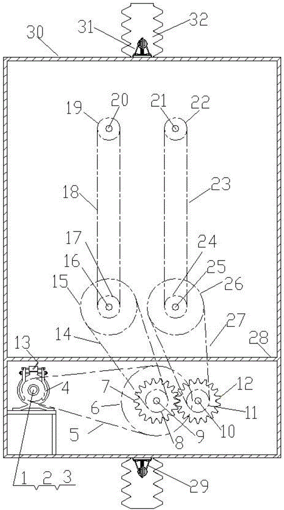
[0022] Embodiment 1, with Figure 1~4 It is also the accompanying drawing of embodiment 1, and the description of the composition and effect of each part of its structure is shown in paragraphs [0005], [0006], and [0007]. The shunt system transmits power to the driving gear of the balanced driving system, and the driving gear meshes with the rack to drive the elevator car system to run. Since it involves the coordination and coordination of multiple transmission systems, special attention should be paid to the manufacturing quality and installation quality during manufacturing and installation to ensure The necessary accuracy can only be tested after passing the test. The test includes ultrasonic flaw detection of the driving gear and rack materials, and the verticality of the rack and guide rail is measured by a laser elevator guide rail verticality measuring instrument; its electrical control The system uses an embedded system as the main control system, and the "power-off s...

Embodiment 2

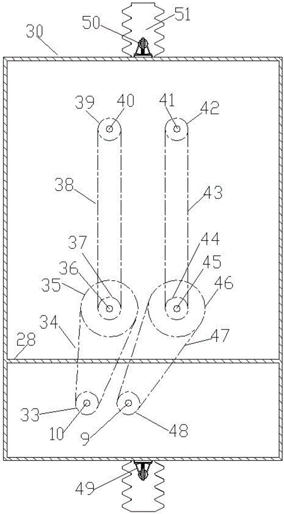
[0023] Embodiment 2, with Figure 5-6 It is also the accompanying drawing of embodiment 2, with Figure 3-4 The content about the driving system in the above is applicable to this embodiment, and the description of the components and functions of its structural parts is shown in paragraphs [0005], [0007] and [0008]. system, the direct drive shunt system transmits power to the drive gear of the balanced drive system, and the drive gear meshes with the rack to drive the elevator car system to run. Since it involves the coordination and coordination of multiple drive systems, special attention should be paid to the quality of manufacture and installation during manufacture and installation. The installation quality must ensure the necessary accuracy, and the test run can only be carried out after passing the test. The test includes ultrasonic flaw detection of the driving gear and rack materials, and the verticality of the guide rail is measured by a laser elevator guide rail ver...

Embodiment 3

[0024] Embodiment 3, with Figure 1~6 Also applicable to Example 3, attached Figure 1~4 The content about the drive system is applicable to this embodiment, and the description of the composition and function of each part of its structure is shown in [0005], [0006], [0007] or [0005], [0007], [0008] As mentioned in paragraph 1, due to the coordination of multiple transmission systems, special attention should be paid to the quality of manufacture and installation during manufacture and installation to ensure the necessary accuracy. Only after passing the test can the trial run be carried out. The test mentioned includes the inspection of the drive gear , The material of the rack is tested by ultrasonic flaw detection, and the verticality of the guide rail is measured by a laser elevator guide rail verticality measuring instrument; its electrical control system uses an embedded system as the main control system, and the "power-off star connection" unit in its electrical control...


PUM

PropertyMeasurementUnit
Pressure angleaaaaaaaaaa

Abstract

The invention provides a synchronous belt main transmission balanced driving rack and pinion elevator. A power transmission system is a synchronous belt main transmission system, the driving system is a balanced driving system, a power dragging system is a permanent magnet DC motor system or a permanent magnet AC synchronous motor system, the balanced driving means that the driving force for driving an elevator car is in left-right symmetry, front-back symmetry, and top-bottom symmetry, The power transmission relation of the synchronous belt main transmission system is that a main power transformation transmission system drives a power shunting transmission system, the power shunting transmission system drives a rack and pinion balanced driving system. A brake wheel coaxial with a motor shaft is equipped with a double-backup power-lossing band-type brake, a 'power-off star connection' unit circuit integrating electrical interlocking and mechanical interlocking is arranged in an electrical control system. The elevator has the beneficial effects of alleviating the self-weight, improving effective transport capacity, and saving energy.

Description

technical field [0001] The invention relates to the field of elevators, in particular to a rack and pinion elevator. Background technique [0002] The rack-and-pinion elevator has its advantages, but the transmission system is installed on the elevator car to increase the weight of the elevator car. In the existing schemes (including some asymmetric drive schemes), the transmission system includes multi-stage transmission, and some There is also a turning (i.e. manual) device, including a hand wheel or handle, a turning gear, a turning clutch, and the entire power system composed of an electric motor. The weight is relatively large, which increases the load on the elevator car, increases energy consumption, and reduces The effective capacity of the elevator car; some schemes adopt single-sided drive, which can reduce some self-weight, but it is only suitable for light load or construction ladders or indoor sundry elevators. Starting from the principle of safe and stable oper...

Claims


Application Information

Patent Timeline
IPC IPC(8): B66B11/04B66B9/02B66B5/02B66B5/18
CPCB66B11/0476B66B5/027B66B5/18B66B9/022B66B11/0461
Inventor 廖忠民
Owner 廖忠民
Why Eureka
Try Eureka