Imaging apparatus
An imaging device and imaging technology, applied in installation, optics, instruments, etc., can solve problems such as unfavorable miniaturization and increase in length, and achieve the effects of being conducive to miniaturization, easy assembly, and high yield rate
- Summary
- Abstract
- Description
- Claims
- Application Information
AI Technical Summary
Problems solved by technology
Method used
Image

Examples
example 1
[0065] The optical characteristic parameters of this example: focal length F=1.33, relative aperture Fno=2.0, field of view FOV=190 degrees.
[0066] Table 1 provides a set of lens parameters:
[0067]
[0068]
[0069] The aspheric coefficients of this example are listed in the following table:
[0070] surface number
S3
S4
S12
S13
K
75.4223
‐0.7847
‐0.45
‐3.4806
A
1.2522E‐004
7.5887E‐004
‐4.6501E‐004
3.8711E‐003
B
‐2.2324e‐005
5.7804e‐005
‐1.8946E‐004
‐2.8180e‐005
C
5.5633e‐007
‐8.5817e‐006
‐7.5788e‐005
‐6.0475e‐005
D
‐4.3473e‐009
3.3873e‐007
‐1.4650e‐006
‐6.0525e‐006
E
‐9.2742e‐027
‐9.2761e‐027
‐9.2771e‐027
9.2741e‐027
[0071] figure 2 is the MTF diagram of the wide-angle lens in this example. The horizontal axis in the figure represents the spatial frequency, unit: line pair per millimeter (lp / mm); the vertical axis represents the ...
Embodiment 2
[0078] The optical characteristic parameters of this example: focal length F=1.28, relative aperture Fno=2.03, field of view FOV=190 degrees.
[0079] Table 2 provides a set of lens parameters:
[0080]
[0081]
[0082] The aspheric coefficients of this example are listed in the following table:
[0083] surface number
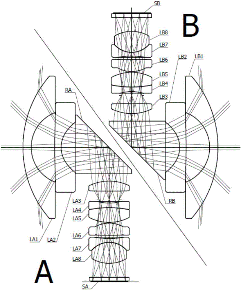
[0084] Figure 6 and Figure 7 They are the structure schematic diagram and the field curvature and axial chromatic aberration schematic diagrams of Example 2 respectively.
Embodiment 3
[0086] The optical characteristic parameters of this example: focal length F=1.35, relative aperture Fno=2.01, field of view FOV=190 degrees.
[0087] Table 3 provides a set of lens parameters:
[0088]
[0089]
[0090] The aspheric coefficients of this example are listed in the following table:
[0091]
[0092]
[0093] Figure 8 and Figure 9 They are the structural schematic diagram and the field curvature and axial chromatic aberration diagrams of Example 3 respectively.
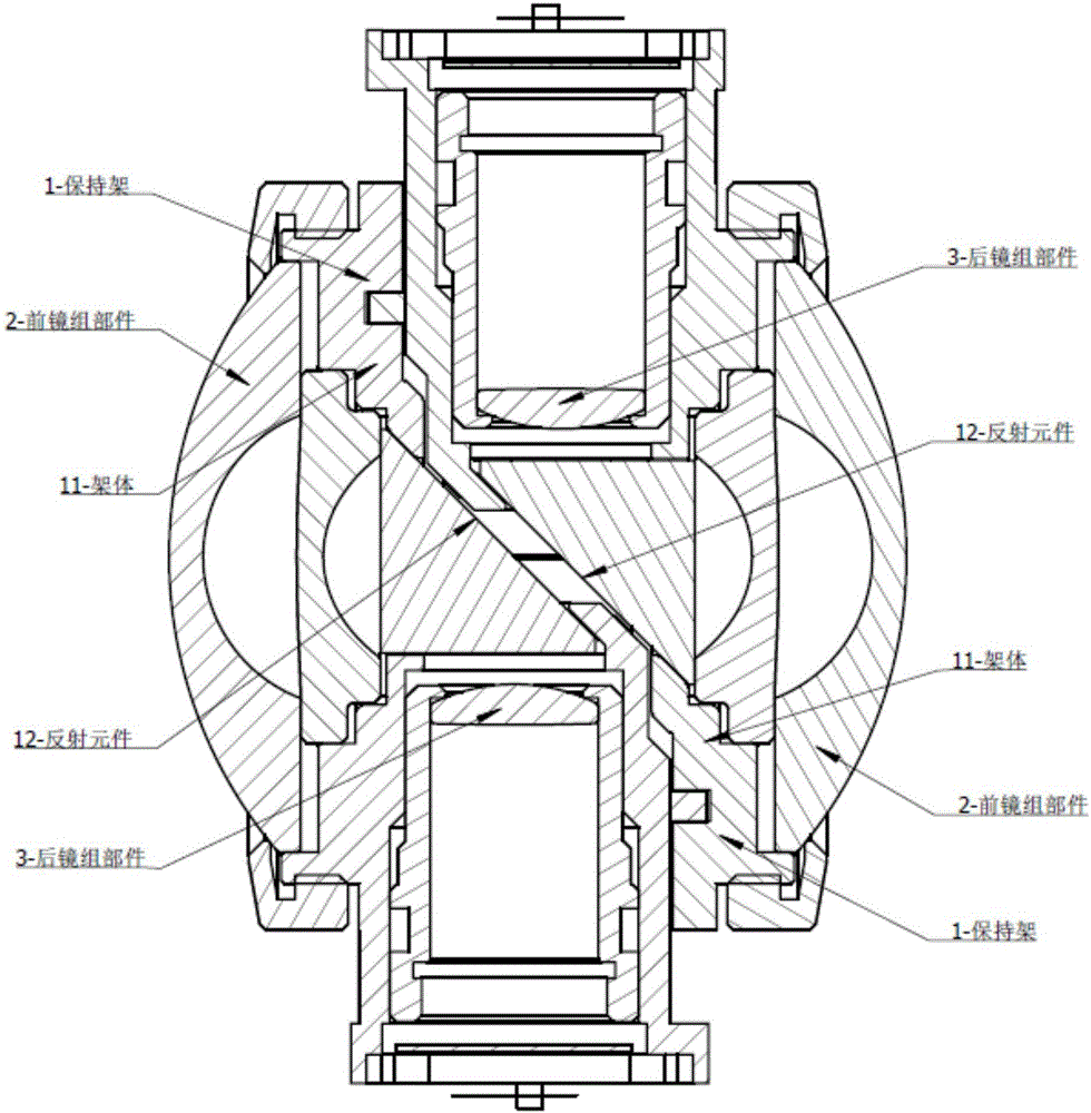
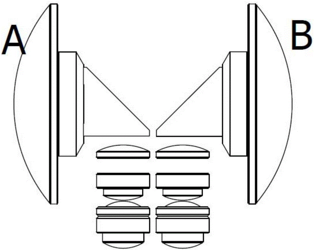
[0094] Figure 10 Shown as a half-section diagram of the wide-angle lens in use in the embodiment, the first wide-angle lens of the first imaging system and the second wide-angle lens of the second imaging system have their own independent holders 1 and reflective elements 12, and the holders are connected by The device is combined so that the optical axes of the front lens group part 2 of the first wide-angle lens and the front lens group part 2 of the second wide-angle lens are in lin...
PUM
| Property | Measurement | Unit |
|---|---|---|
| Field of view | aaaaa | aaaaa |
Abstract
Description
Claims
Application Information
 - Generate Ideas
- Intellectual Property
- Life Sciences
- Materials
- Tech Scout
- Unparalleled Data Quality
- Higher Quality Content
- 60% Fewer Hallucinations
Browse by: Latest US Patents, China's latest patents, Technical Efficacy Thesaurus, Application Domain, Technology Topic, Popular Technical Reports.
© 2025 PatSnap. All rights reserved.Legal|Privacy policy|Modern Slavery Act Transparency Statement|Sitemap|About US| Contact US: help@patsnap.com