Welding method for cooling tank in new energy electric vehicle

A technology of electric vehicles and welding methods, applied in welding equipment, welding/welding/cutting items, applications, etc., can solve problems such as easy generation of pores, welding deformation, and serious softening of aluminum alloy welded joints, and achieve good sealing and deformation The effect of small size and simple welding process

Active Publication Date: 2016-12-07
安徽新富新能源科技股份有限公司
View PDF9 Cites 5 Cited by
  • Summary
  • Abstract
  • Description
  • Claims
  • Application Information

AI Technical Summary

Problems solved by technology

[0005] 1) The welded joints of aluminum alloy are severely softened and the strength coefficient is low;
[0006] 2), the surface of aluminum alloy is easy to produce refractory oxide film (Al 2 o 3 ), a welding process with high power density is required;
[0007] 3) Aluminum alloy welding is prone to air holes and thermal cracks;
[0008] 4), aluminum alloy welding linear expansion coefficient is large, easy to produce welding deformation;
[0010] Among them, the aluminum alloy welded joints are softened, the strength coefficient is greatly reduced, and the joint strength is much lower than that of the base metal, resulting in a decrease in joint performance, which limits the wide application of aluminum alloys in welded structures to a certain extent.

Method used


Image

  • Welding method for cooling tank in new energy electric vehicle
  • Welding method for cooling tank in new energy electric vehicle
  • Welding method for cooling tank in new energy electric vehicle

Examples


Embodiment Construction

[0037] In order to make the object, technical solution and advantages of the present invention clearer, the present invention will be further described in detail below in conjunction with the accompanying drawings and embodiments. It should be understood that the specific embodiments described here are only used to explain the present invention, not to limit the present invention.

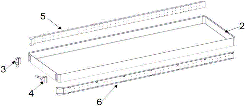
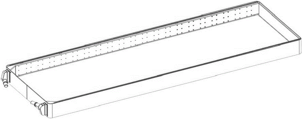
[0038] The invention is used for the welding method of the cooling box in the new energy electric vehicle, which is aimed at the special process of the cooling box. Such as Figure 1 to Figure 6 As shown, the cooling box, that is, the battery cooling device, includes a lower cover plate 1, an outer frame 2, an inlet side plate 3, an outlet side plate 4, an inlet end 5, an outlet end 6, a battery support tube 7, an upper cover plate 8, a support Column 9.

[0039] The inlet end 5, the outlet end 6, the inlet side panel 3, and the outlet side panel 4 are respectively assembled on the outer frame 2....


PUM

PropertyMeasurementUnit
thicknessaaaaaaaaaa
thicknessaaaaaaaaaa
diameteraaaaaaaaaa

Abstract

The invention discloses a welding method for a cooling tank in a new energy electric vehicle. The cooling tank comprises a lower cover plate, an outer frame, an inlet side edge plate, an outlet side edge plate, an inlet tail end, an outlet tail end, a battery supporting cylinder, an upper cover plate and multiple supporting pillars. The welding method includes the following steps that the inlet side edge plate and the outlet side edge plate are symmetrically assembled on one outer side of the outer frame. The inlet tail end and the outlet tail end are assembled on the two opposite inner sides of the outer frame correspondingly, and the inlet tail end and the outlet tail end communicate with the inlet side edge plate and the outlet side edge plate correspondingly to form a water tank water guide system. The battery supporting cylinder and the supporting pillars are inserted in corresponding holes in the lower cover plate, after installation, the lower cover plate is then inserted in an insertion groove in the outer frame, and it is ensured that the installation gap between the lower cover plate and the outer frame is within 0.2 mm. The upper cover plate is installed, and meanwhile it is ensured that the installation gap between the upper cover plate and the outer frame is within 0.2 mm. The edge part of the cooling tank is welded through lasers, and the cooling tank is welded in a tin immersion manner. The welding method is suitable for sealing welding of related aluminum and aluminum alloys, and the welding technology is simple.

Description

technical field [0001] The invention relates to a welding method, in particular to a welding method for a cooling box in a new energy electric vehicle. Background technique [0002] Aluminum and aluminum alloys adopt a large number of new production processes and improved technologies, as well as their price stability, which has led many automakers to greatly increase their plans for aluminum applications. In the process of lightweighting automobile bodies, more and more aluminum alloys are used, reducing vehicle weight as an effective measure to reduce fuel consumption and exhaust emissions; also in the new energy electric vehicle industry, reducing vehicle weight directly affects the battery life of the vehicle . [0003] Aluminum alloy has the characteristics of low density, high strength, non-magnetism, good corrosion resistance, low temperature toughness and formability, and is widely used in various welding structures, becoming an ideal lightweight material. The bodi...

Claims


Application Information

Patent Timeline
Patent Type & Authority Applications(China)
IPC IPC(8): B23K28/02B23K101/14B23K103/10
CPCB23K28/02B23K2101/14B23K2103/10
Inventor 程传峰
Owner 安徽新富新能源科技股份有限公司
Why Eureka
Try Eureka