Method for reducing heat of hypersonic velocity aircraft based on shock wave control

A hypersonic and aircraft technology, applied in aircraft, supersonic aircraft, aircraft control, etc., can solve the problems of long-term high temperature resistance/ablation resistance, high heating capacity of thermal structure, and impact on flight safety, etc. , to achieve the effect of easy electric parameter control, large jet flow and light weight

Inactive Publication Date: 2016-12-07
NAT UNIV OF DEFENSE TECH
View PDF4 Cites 21 Cited by
  • Summary
  • Abstract
  • Description
  • Claims
  • Application Information

AI Technical Summary

Problems solved by technology

[0006] However, hypersonic vehicles have to fly in the atmosphere for a long time. Different from the short-term high-heat environment reentry conditions of traditional ballistic strategic warheads, the thermal environment of hypersonic vehicles is characterized by long-term, high enthalpy, and medium / low heat flow. The total heating capacity of the thermal structure is greater, and the requirements for long-term high temperature resistance / ablation resistance are more stringent. If you do not use new technologies to improve the thermal environment and unilaterally use extreme design methods to continuously thin the heat-resistant layer, not only can you discover Potential is limited, and it will also seriously affect flight safety

Method used


Image

  • Method for reducing heat of hypersonic velocity aircraft based on shock wave control
  • Method for reducing heat of hypersonic velocity aircraft based on shock wave control
  • Method for reducing heat of hypersonic velocity aircraft based on shock wave control

Examples


Embodiment Construction

[0039] In order to make the object, technical solution and advantages of the present invention clearer, the implementation manner of the present invention will be further described in detail below in conjunction with the accompanying drawings.

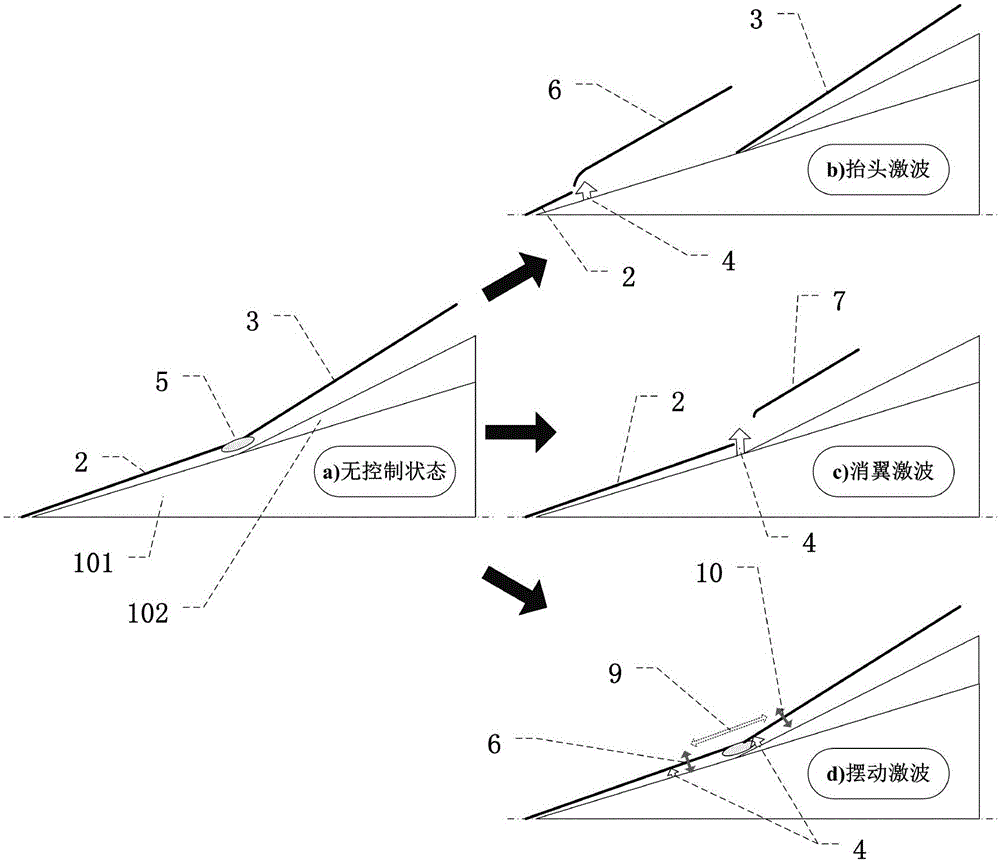
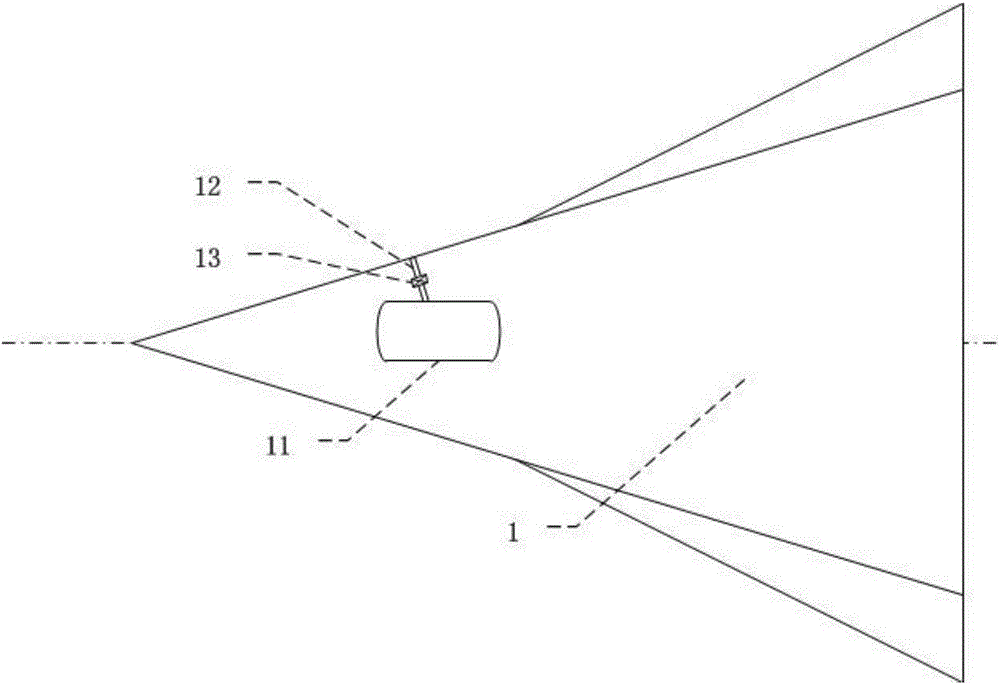
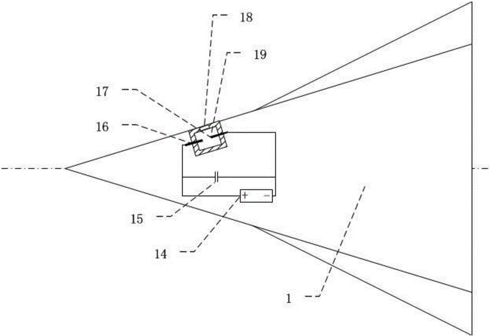
[0040] A heat reduction method for a hypersonic vehicle based on shock wave control. The shock wave in the area that needs to be cooled on the hypersonic vehicle 1 is controlled by injecting the jet 4. Under the action of the gas jet, the flow field of the hypersonic vehicle The position and intensity of the shock wave are changed, thereby eliminating or controlling the shock wave interference area where the peak heat flow is located, so as to achieve the purpose of reducing heat.

[0041] figure 1 As shown in (a), in the uncontrolled state, the head shock wave 2 and the wing leading edge shock wave 3 (wing shock wave) interfere with each other to form a shock wave interference area 5, and the thermal environment in the local area of ​...


PUM


Abstract

The invention discloses a method for reducing heat of a hypersonic velocity aircraft based on shock wave control, and relates to the fields of flowing control of hydromechanics and plasma physical application. The method comprises the following steps of using a high-pressure gas source gas spraying device or a plasma synthesizing flow jetting device to control shock waves in a hypersonic velocity aircraft flow field, lifting the leading head shock wave of the hypersonic velocity aircraft, and eliminating the leading shock of side wings, or producing reciprocating swinging, so as to eliminate or control the shock wave disturbance area, reduce the heat flow in key periods and key areas, and realize the heat protection of the aircraft. The method has the advantages that by adopting the outer flow field control type, the root produced by high heat flow is prevented or controlled, and the heat reducing and protection can be realized by reducing the production of heat flow in source; compared with the traditional method of performing passive heat protection on the cause of high heat flow, the material revolution is realized, and a new active heat protection control technique is realized.

Description

technical field [0001] The invention relates to the field of fluid mechanics flow control and the application field of plasma physics. It is a method for reducing heat of a hypersonic aircraft based on shock wave control, which can effectively reduce the difficulty of designing the thermal structure of the hypersonic aircraft and the thickness of thermal protection, and improve the hypersonic speed. overall aircraft performance. Background technique [0002] Hypersonic vehicle technology is a new commanding height in the field of aerospace technology in the 21st century. It is the third epoch-making milestone in the history of human aerospace after the invention of aircraft and breaking the sound barrier. It will also open up a new way for humans to enter space. Hypersonic aircraft has the characteristics of long flight distance, strong maneuverability, and high penetration probability. It can obtain the ability to ensure space entry, effective use of space, and space contro...

Claims


Application Information

Patent Timeline
Patent Type & Authority Applications(China)
IPC IPC(8): B64C30/00B64C21/04B64C21/08B64C23/04
CPCB64C21/04B64C21/08B64C23/04B64C30/00
Inventor 王林罗振兵周岩夏智勋蒋浩
Owner NAT UNIV OF DEFENSE TECH
Why Eureka
Try Eureka