Quick disconnect attachment system, parachute system, attachment and disconnection method

A connection system and fast detachment technology, applied in the field of parachute systems, can solve problems such as poor safety, poor versatility, and complex structure, and achieve the effects of simple structure, cost saving, and increased detachment speed

Active Publication Date: 2018-06-15
北京耐威智能科技有限公司
View PDF6 Cites 0 Cited by
  • Summary
  • Abstract
  • Description
  • Claims
  • Application Information

AI Technical Summary

Problems solved by technology

[0004] Therefore, the technical problem to be solved by the embodiment of the present invention is that the detachable connection device in the prior art has poor safety, poor versatility, and complicated structure.

Method used


Image

  • Quick disconnect attachment system, parachute system, attachment and disconnection method
  • Quick disconnect attachment system, parachute system, attachment and disconnection method
  • Quick disconnect attachment system, parachute system, attachment and disconnection method

Examples


Embodiment 1

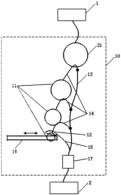
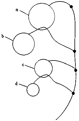
[0051] This embodiment provides a quick-disengageable connection system, which can be applied to any required system, and is especially suitable for the connection between a flying device (such as a drone) and a parachute. like figure 1 As shown, a quick-disconnect connection system 10 is used for connecting a first to-be-connected part 1 and a second to-be-connected part 2 . The quick disconnect connection system 10 comprises: a base ring 21, at least two sub-rings 11 ( figure 1 Three sub-rings 11) and locking bar 16 are shown in . The base ring 21 is used for connecting with the first component to be connected. The sub-ring 11 is connected to the first connecting band 13 through the second connecting band 14, the first connecting band 13 is connected to the second part to be connected, and the sub-ring 11 passes through the hole in the middle of the base ring 21 or any The hole in the middle of other sub-rings 11. The locking rod 16 is used for inserting into the hole in...

Embodiment 2

[0060] This embodiment provides a quick-disconnect connection system, in addition to including the components of Embodiment 1 above, such as Figure 4 As shown, a clasp 12 is also included. The buckle 12 is connected to the first connecting belt 13 through the third connecting belt 15 , and the buckle 12 is used to pass through the sub-ring 11 where the locking rod 16 is inserted during connection. The clasp 12 can be set through one sub-ring, and can also be set through a plurality of sub-rings. By setting the clasp, when connecting, the clasp is put through the sub-ring first, and then the locking rod is inserted into the sub-ring, thereby further ensuring the reliability of the connection and improving the firmness of the connection system.

Embodiment 3

[0062] This embodiment provides a quick disconnect connection system, in addition to including the components of Embodiments 1 and 2 above, such as Figure 5 As shown, it also includes a retractable belt device 17 (such as a pulley, etc.). The first connecting belt 13 is connected to the second to-be-connected part 2 through a retractable belt device 17 , and the retractable belt device 17 is used to increase or shorten the length of the first connecting belt 13 . When detaching, the control system can control the retractable belt device 17 to tighten the first connecting belt 13, shorten the length of the first connecting belt 13, and achieve the purpose of quickly extracting the ion ring, thereby further improving the detachment speed of the connecting system. The advantage of a quick breakaway.


PUM


Abstract

The present invention discloses a connection system, parachute system, connection, and detachment method that can be quickly detached. It is a connection device technology field. Among them, the connection system that can be quickly separated includes: the base ring, which is used to connect with the first connection parts; at least at leastTwo sub -rings, the sub -ring is connected to the first connection band through the second connection belt. The first connection belt is connected to the second to be connected.The holes in the middle of the ring; the lock rod is used to insert the hole in the middle of the rings during the connection.The present invention has the advantages of simple structure, low cost, high safety, high versatility, and reusable use.

Description

technical field [0001] The invention relates to the technical field of connection devices, in particular to a fast-disconnectable connection system, a parachute system, and a connection and separation method. Background technique [0002] The detachable connection device is widely used, and is involved in many fields that need to be applied to the detachable connection. For example, flying equipment (especially drones) and parachutes need to be connected through a detachable connection device. When the drone lands on the ground, the parachute needs to be decelerated. When the drone lands, in order to prevent The UAV is blown away by the wind, and the detachable connection device needs to be activated to separate the parachute from the UAV. [0003] The traditional parachute disengagement method is very complicated. First, a cutting device needs to be installed at the root of the parachute. The cutting device is mainly composed of blades, pistons, gunpowder and other compone...

Claims


Application Information

Patent Timeline
Patent Type & Authority Patents(China)
IPC IPC(8): B64D17/38B64D17/80
CPCB64D17/38B64D17/80B64U70/83
Inventor 郝超雪陈明军张昆曹立金
Owner 北京耐威智能科技有限公司
Why Eureka
Try Eureka