Straw power generation device

A technology of power generation device and straw, which is applied in combustion methods, solid fuels, lighting and heating equipment, etc., can solve the problems of cumbersome operation, single structure, and insufficient environmental protection.

Inactive Publication Date: 2016-12-07
HEFEI HEYI ENVIRONMENTAL PROTECTION TECH ENG
View PDF5 Cites 4 Cited by
  • Summary
  • Abstract
  • Description
  • Claims
  • Application Information

AI Technical Summary

Problems solved by technology

[0006] In order to overcome the disadvantages of the current power generation device that are not environmentally friendly, cumbersome to operate, and have a single structure, the technical problem to be solved by the present invention is to provide a straw power generation device that is environmentally friendly, easy to operate, and novel in structure

Method used


Image

  • Straw power generation device
  • Straw power generation device
  • Straw power generation device

Examples


Embodiment 1

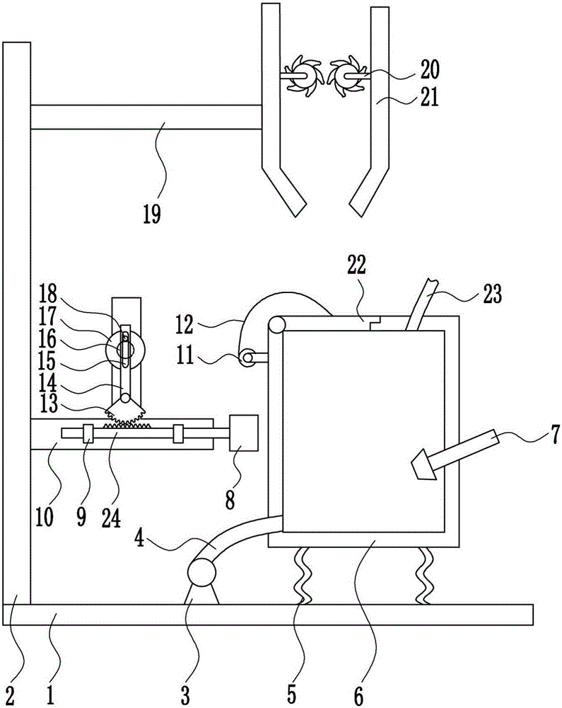
[0040] A straw power generation device, such as figure 1 As shown, it includes base plate 1, left frame 2, air pump 3, first air pipe 4, first spring 5, combustion box 6, flame spray gun 7, impact block 8, guide sleeve 9, T-shaped bracket 10, electric reel 11. Pull wire 12, sector gear 13, swing lever 14, motor 16, turntable 17, block 18, top plate 19, electric crushing wheel 20, crushing bucket 21, box cover 22 and second air pipe 23, bottom plate 1 top left side set Left frame 2 is arranged, and left frame 2 right side lower part is provided with T-shaped support 10, and T-shaped support 10 lower front side is symmetrically provided with guide sleeve 9, and guide sleeve 9 slide type is provided with special-shaped rack 24, and special-shaped rack 24 right-hand side A collision block 8 is provided, and the middle part of the front side of the T-shaped bracket 10 is hingedly connected with a sector gear 13. The sector gear 13 meshes with the special-shaped rack 24. The top of ...

Embodiment 2

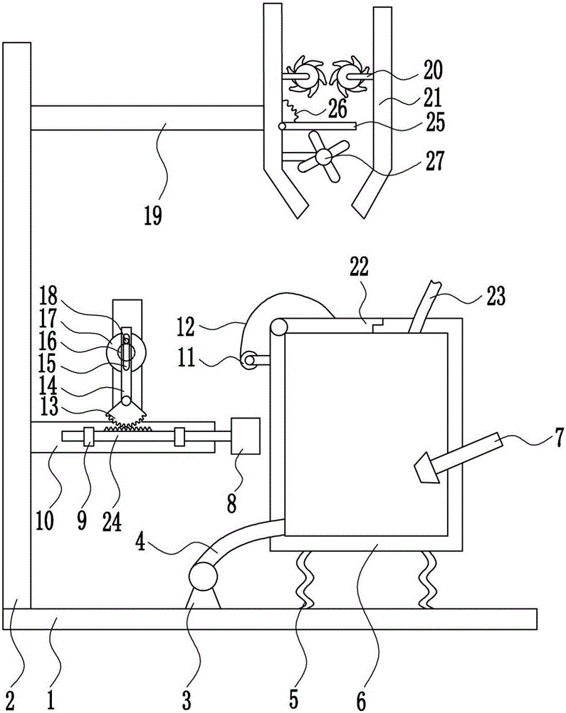
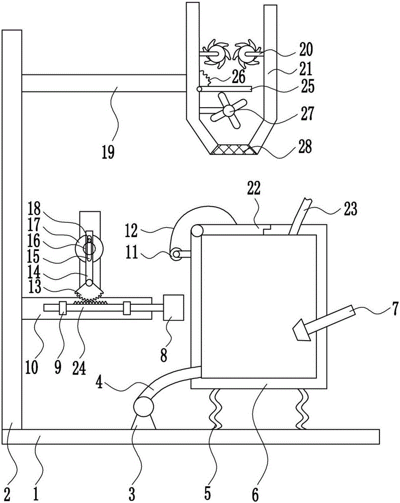
[0042] A straw power generation device, such as Figure 1-9 As shown, it includes base plate 1, left frame 2, air pump 3, first air pipe 4, first spring 5, combustion box 6, flame spray gun 7, impact block 8, guide sleeve 9, T-shaped bracket 10, electric reel 11. Pull wire 12, sector gear 13, swing lever 14, motor 16, turntable 17, block 18, top plate 19, electric crushing wheel 20, crushing bucket 21, box cover 22 and second air pipe 23, bottom plate 1 top left side set Left frame 2 is arranged, and left frame 2 right side lower part is provided with T-shaped support 10, and T-shaped support 10 lower front side is symmetrically provided with guide sleeve 9, and guide sleeve 9 slide type is provided with special-shaped rack 24, and special-shaped rack 24 right-hand side A collision block 8 is provided, and the middle part of the front side of the T-shaped bracket 10 is hingedly connected with a sector gear 13. The sector gear 13 meshes with the special-shaped rack 24. The top ...


PUM

PropertyMeasurementUnit
diameteraaaaaaaaaa
diameteraaaaaaaaaa
thicknessaaaaaaaaaa

Abstract

The invention relates to a power generation device, in particular to a straw power generation device. Against to-be-solved technical problems, the invention provides the straw power generation device which is environmentally friendly, convenient to operate and novel in structure. In order to solve the technical problems, the straw power generation device comprises a base plate, a left frame, an air pump, a first air pipe, a first spring, a combustion box, a flame spraying gun, an impact block, guide sleeves, a T-shaped support, an electric winding wheel and a pull wire and the like. The left frame is disposed on the left side of the top of the base plate, the T-shaped support is arranged on the lower portion of the right side of the left frame, the guide sleeves are symmetrically arrange on the front side of the lower portion of the T-shaped support, a special-shaped rack is slidably arranged on the guide sleeves, the right end of the special-shaped rack is provided with the impact block, and a sector gear is hinged to the middle of the front side of the T-shaped support. The straw power generation device is environmentally friendly, convenient to operate and novel in structure. The device always plays an important role, not only is good in power generation effect, but also improves working efficiency, and workers can use the device conveniently.

Description

technical field [0001] The invention relates to a power generation device, in particular to a straw power generation device. Background technique [0002] Straw is the general term for the stems and leaves (ears) of mature crops. It usually refers to the remaining part of wheat, rice, corn, potato, rapeseed, cotton, sugar cane and other crops (usually coarse grains) after harvesting the seeds. More than half of the photosynthetic products of crops exist in straw, which is rich in nitrogen, phosphorus, potassium, calcium, magnesium and organic matter, etc. It is a multi-purpose renewable biological resource, and straw is also a roughage. It is characterized by high crude fiber content (30%-40%), and contains lignin and so on. Although lignocellulose cannot be utilized by pigs and chickens, it can be absorbed and utilized by ruminant cattle, sheep and other livestock. [0003] Straw is a good clean renewable energy and one of the new energy sources with the most potential f...

Claims


Application Information

Patent Timeline
Patent Type & Authority Applications(China)
IPC IPC(8): C10L5/44H02K7/18F23K3/00
CPCY02E50/10Y02E50/30C10L5/445F23K3/00H02K7/18
Inventor 韩晓春
Owner HEFEI HEYI ENVIRONMENTAL PROTECTION TECH ENG
Why Eureka
Try Eureka