
A device for rapid thinning of silicon wafers for solar cell production process

A solar cell and production process technology, applied in the direction of circuits, crystal growth, electrical components, etc., can solve the problems of uneven thinning thickness, slow thinning speed, cumbersome operation, etc., and achieve uniform thinning thickness and fast thinning speed , the effect of simple operation

Active Publication Date: 2018-09-28
江西宇泰新能源有限公司
View PDF5 Cites 0 Cited by
  • Summary
  • Abstract
  • Description
  • Claims
  • Application Information

AI Technical Summary

Problems solved by technology

[0006] In order to overcome the shortcomings of the existing silicon wafer thinning device for solar cell production technology, such as slow thinning speed, cumbersome operation, and uneven thinning thickness, the technical problem to be solved by the present invention is to provide a silicon wafer thinning device with fast thinning speed, Si wafer rapid thinning device for solar cell production process with simple operation and uniform thinning thickness

Method used


Image

  • A device for rapid thinning of silicon wafers for solar cell production process
  • A device for rapid thinning of silicon wafers for solar cell production process

Examples


Embodiment 1

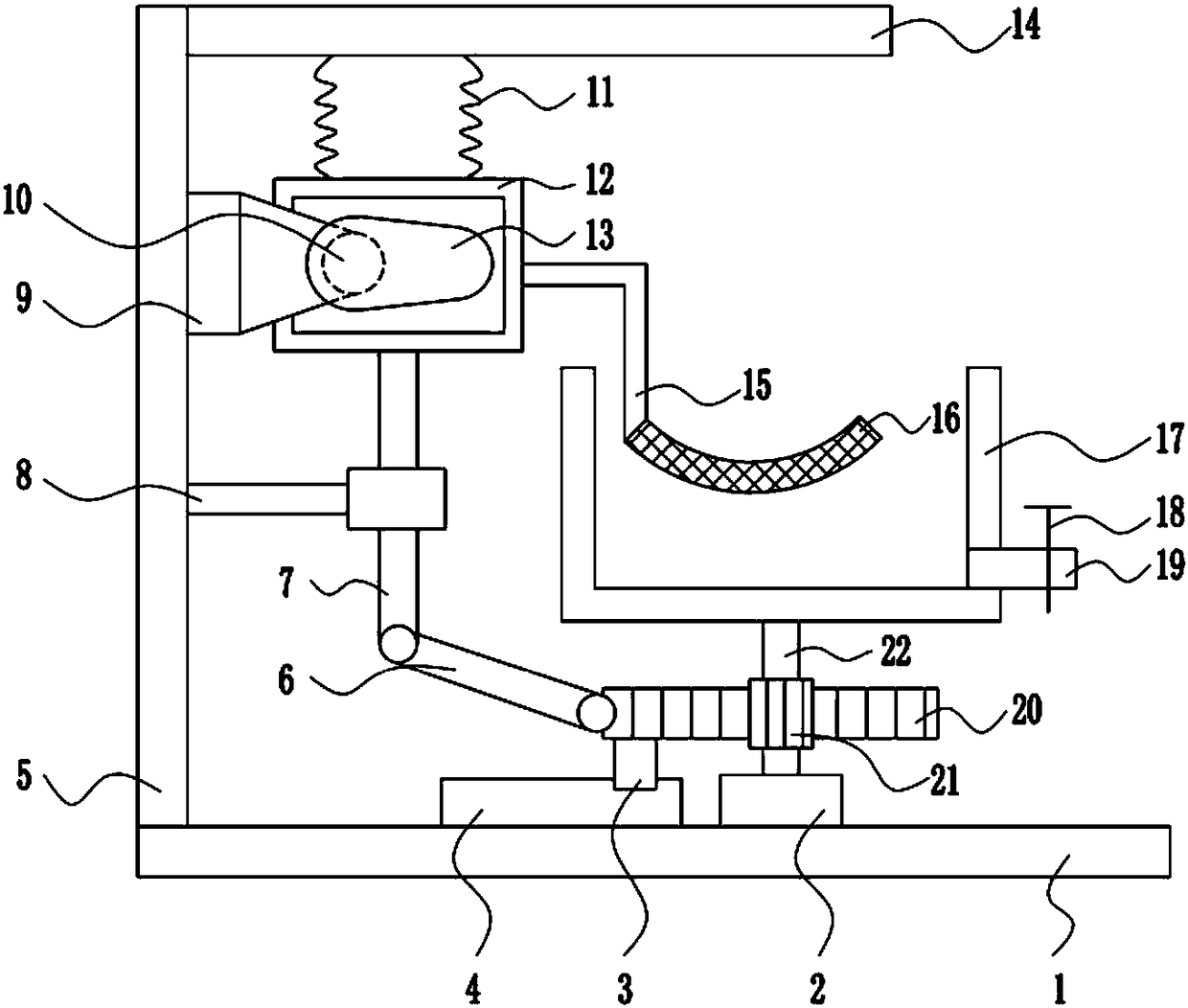
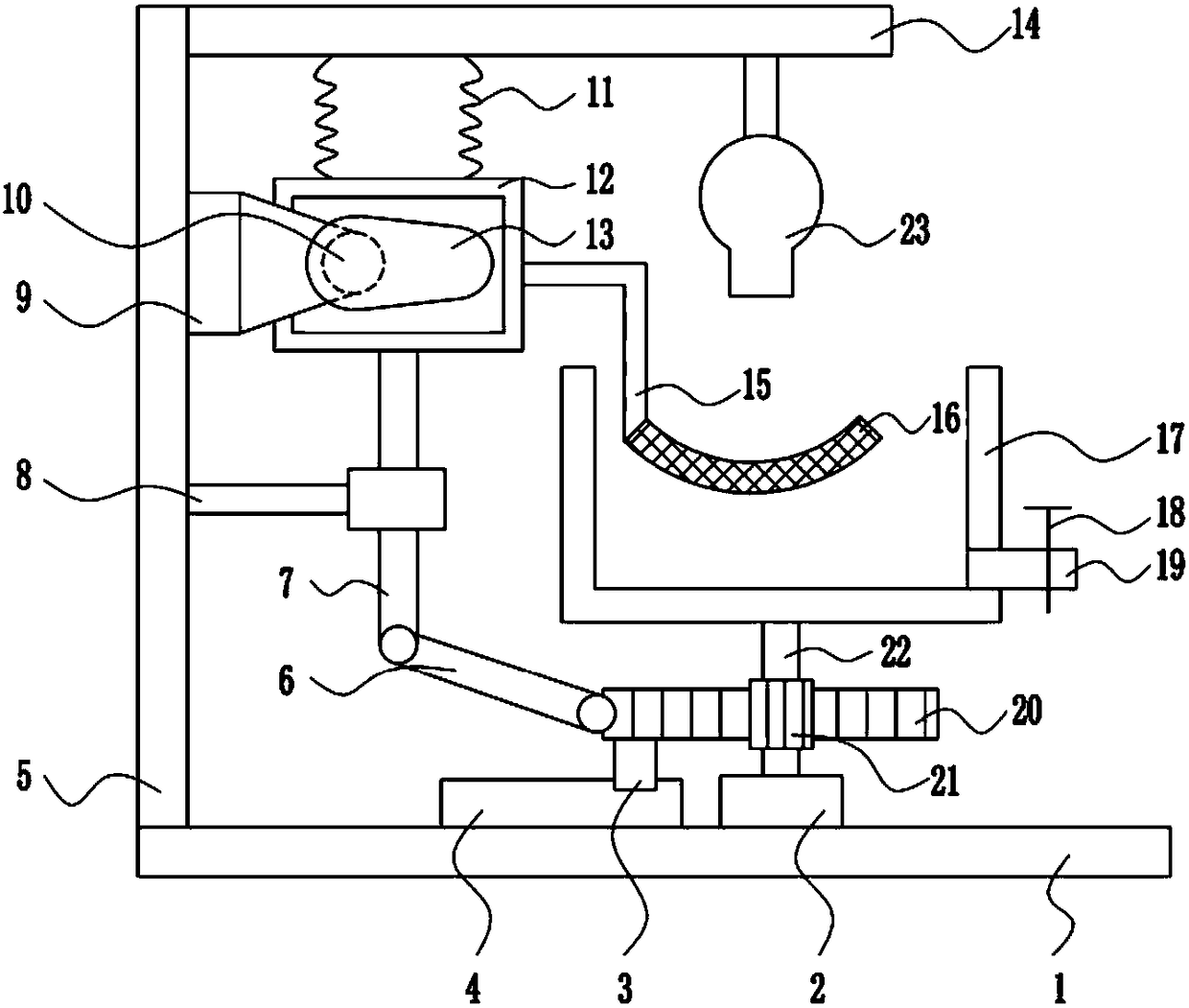
[0019] A kind of silicon wafer rapid thinning device for solar cell production process, such as Figure 1-2 As shown, it includes base plate 1, bearing seat 2, slider 3, slide rail 4, left frame 5, swing rod 6, lifting rod 7, guide sleeve 8, mounting seat 9, motor 10, spring 11, moving frame 12, Cam 13, top plate 14, L-shaped connecting rod 15, arc-shaped screen plate 16, processing frame 17, electric control valve 18, liquid outlet pipe 19, rack 20, gear 21 and rotating shaft 22, and the top of bottom plate 1 from left to right A left frame 5, a slide rail 4 and a bearing seat 2 are provided, a slide block 3 is slidably connected on the slide rail 4, a rack 20 is provided on the slide block 3, a rotating shaft 22 is provided on the bearing seat 2, and a rotating shaft 22 is provided on the rotating shaft 22 Gear 21, gear 21 meshes with rack 20, processing frame 17 is arranged on the top of rotating shaft 22, liquid outlet pipe 19 is arranged under the right wall of processing...


PUM


Abstract

The invention relates to a silicon wafer thinning device, in particular to a rapid silicon wafer thinning device for a solar cell production technology, and aims to provide a rapid silicon wafer thinning device which is used for the solar cell production technology and is high in thinning speed, simple to operate and uniform in thinning thickness. The rapid silicon wafer thinning device comprises a bottom plate, a bearing block, a sliding block, a sliding rail, a left frame, a swing rod, a lifting rod, a guiding sleeve, a mounting seat, a motor, springs, a moving frame, a cam, a top plate, an L-shaped connecting rod, an arc-shaped net plate, a processing frame, an electric control valve, a liquid outlet pipe, a rack, a gear and a rotating shaft, wherein the left frame, the sliding rail and the bearing block are arranged at the top of the bottom plate sequentially from left to right; the sliding block is glidingly connected onto the sliding rail; and the rack is arranged on the sliding block. The device has the effects of being high in thinning speed, simple to operate and uniform in thinning thickness.

Description

technical field [0001] The invention relates to a silicon chip thinning device, in particular to a silicon chip rapid thinning device for a solar cell production process. Background technique [0002] Solar energy refers to the thermal radiation energy of the sun, and its main manifestation is the sun's rays that are often said. In modern times, it is generally used to generate electricity or provide energy for water heaters. Since the birth of life on earth, it has mainly survived on the heat radiation energy provided by the sun. Since ancient times, humans have also known to use sunlight to dry objects and use it as a method of making food, such as making salt and drying salted fish. With fossil fuels decreasing day by day, solar energy has become an important part of the energy used by human beings and has been continuously developed. There are two ways to use solar energy: photothermal conversion and photoelectric conversion. Solar power is a new type of renewable ener...

Claims


Application Information

Patent Timeline
Patent Type & Authority Patents(China)
IPC IPC(8): C23F1/08C30B33/10C30B29/06H01L31/18
CPCC23F1/08C30B29/06C30B33/10H01L31/18Y02P70/50
Inventor 关松生
Owner 江西宇泰新能源有限公司
Learn More