Multistage thermo-acoustic generator set and multistage heat regenerative refrigeration system provide with same

A technology for generator sets and thermoacoustic engines, which is applied in refrigerators, engine components, refrigeration and liquefaction, etc., can solve the problems of low efficiency, large loss of resonance tubes, and increased scavenging volume, so as to improve the working efficiency of the system and improve the thermoelectric efficiency. , the effect of high thermoelectric conversion efficiency

Active Publication Date: 2016-12-07
TECHNICAL INST OF PHYSICS & CHEMISTRY - CHINESE ACAD OF SCI
View PDF6 Cites 18 Cited by
  • Summary
  • Abstract
  • Description
  • Claims
  • Application Information

AI Technical Summary

Problems solved by technology

Although there is no electro-acoustic conversion process of the compressor in this structure, the efficiency can be improved, but the phase angle of the pressure wave and the volume flow at the generator piston is close to 90° ( figure 1 The corresponding phase angle in the structure is about 60°), which makes the scavenging volume of the generator piston increase several times under the same power generation, which brings great difficulty to the design of the motor, so it is not widely used
[0006] At present, there are also structural forms of acoustic double-acting engines and mechanical double-acting engines. The former resonant tube has large losses and low efficiency, and the latter system has the problem of system instability, so it has not been widely used.
[0007] In summary, existing thermoacoustic generators have disadvantages such as low efficiency and difficult motor matching design; in addition, the temperature of the heater of the current thermoacoustic generator is usually a fixed value, and it is difficult to use heat energy of different temperature grades in stages

Method used


Image

  • Multistage thermo-acoustic generator set and multistage heat regenerative refrigeration system provide with same
  • Multistage thermo-acoustic generator set and multistage heat regenerative refrigeration system provide with same
  • Multistage thermo-acoustic generator set and multistage heat regenerative refrigeration system provide with same

Examples


Embodiment 1

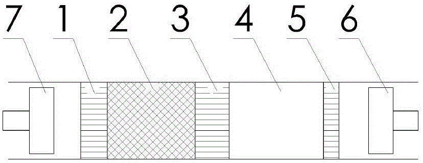
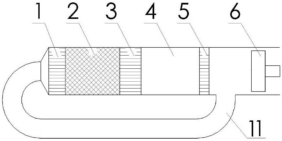
[0034] Such as image 3 As shown, the multi-stage thermoacoustic generator set provided by this embodiment includes multiple sets of thermoacoustic engines, and multiple sets of thermoacoustic engines are connected in series between the compressor and the generator, and each set of thermoacoustic engines is connected by a harmonic oscillator Component coupling, resonant sub-components are used to form traveling wave sound fields in each group of thermoacoustic engines at the same time, using resonant sub-components to achieve good matching between adjacent two groups of thermoacoustic engine groups, in each group of thermoacoustic engine groups The internal energy can form a traveling wave sound field at the same time, thereby improving the thermoelectric efficiency of the thermoacoustic generator set. Cascade utilization of thermal energy.

[0035] The thermoacoustic engine includes a main water cooler 1, a regenerator 2, a heater 3, a thermal buffer pipe 4 and a secondary w...

Embodiment 2

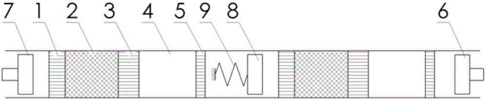
[0045] The multi-stage thermoacoustic generator set of the second embodiment is basically the same as the multi-stage thermoacoustic generator set described in the first embodiment, and the similarities will not be repeated. The difference lies in: the multi-stage thermoacoustic generator set of the second embodiment Among them, there are three sets of thermoacoustic engines installed in sequence between the compressor and the generator, and each two sets of thermoacoustic engines are coupled through the resonant sub-assembly. When the resonant sub-assembly is installed, the resonant spring 9 and the mass piston 8 connected, the mass piston 8 can reciprocate toward the sound wave inlet direction of the thermoacoustic engine.

[0046] On the basis of Embodiment 1, the multi-stage thermoacoustic generating set of Embodiment 2 increases the number of thermoacoustic engines to three, such as Figure 4 As shown, therefore, the thermoelectric efficiency of this multi-stage thermoaco...

Embodiment 3

[0049] Such as Figure 5 As shown, the multi-stage thermoacoustic engine unit of the third embodiment is basically the same as the multi-stage thermoacoustic engine unit described in the first embodiment, and the similarities will not be repeated. The difference lies in: the resonator assembly of the third embodiment During installation, a bypass groove is provided between the mechanical energy outlet and the sound wave inlet of two adjacent groups of thermoacoustic engines, and the mass piston 8 is installed in the bypass groove through a resonant spring 9 .


PUM


Abstract

The invention relates to the technical field of thermo-acoustic generator devices, in particular to a multistage thermo-acoustic generator set and a multistage heat generative refrigeration system provided with the same. The multistage thermo-acoustic generator set comprises a plurality of sets of thermo-acoustic engines which are sequentially connected between a compressor and a generator in series. Every two adjacent sets of thermo-acoustic engines are coupled through a harmonic oscillator assembly. The harmonic oscillator assemblies are used for enabling travelling wave sound fields to be formed in the corresponding sets of thermo-acoustic engines simultaneously. Every two adjacent two sets of thermo-acoustic engines are matched well by utilization of one harmonic oscillator assembly. The travelling wave sound fields can be simultaneously formed in the multiple sets of the thermo-acoustic engines, so that the thermoelectric efficiency of the thermo-acoustic generator set is improved. Meanwhile, the working temperatures of the multiple sets of the thermo-acoustic engines are set to be different, and accordingly gradient utilization of different-grade heat energy can be further achieved through the multistage thermo-acoustic generator set, so that the multistage heat regenerative refrigeration system provided with the multistage thermo-acoustic generator set has the higher thermoelectric conversion efficiency.

Description

technical field [0001] The invention relates to the technical field of thermoacoustic generator equipment, in particular to a multistage thermoacoustic generator set and a multistage regenerative refrigeration system with the set. Background technique [0002] A thermoacoustic engine is a new type of power device that converts thermal energy into mechanical energy. If it is connected to a generator, the conversion of mechanical energy into electrical energy constitutes a thermoacoustic generator. Thermoacoustic generator is a kind of external combustion power generation equipment, which can use waste heat, solar energy, industrial waste heat, etc. to generate electricity, so it has a wide range of application prospects. [0003] Existing thermoacoustic engines such as figure 1 As shown, its core components include a main water cooler 1 , a regenerator 2 , a heater 3 , a thermal buffer pipe 4 and a secondary water cooler 5 . When the mechanical energy in the form of sound w...

Claims


Application Information

Patent Timeline
Patent Type & Authority Applications(China)
IPC IPC(8): F01N5/02F02G5/02
CPCF01N5/025F02G5/02F01N5/02F25B9/14Y02T10/12
Inventor 胡剑英罗二仓张丽敏吴张华
Owner TECHNICAL INST OF PHYSICS & CHEMISTRY - CHINESE ACAD OF SCI
Why Eureka
Try Eureka