Water pump control method based on pressure sensor and controller
A technology of pressure sensor and control method, applied in pump control, engine control, non-variable-capacity pump, etc., can solve the problems of waste, water pump damage to electric energy, increase of pump start and stop frequency, etc., to improve the degree of automation control and improve automation degree, reducing the effect of user operations
- Summary
- Abstract
- Description
- Claims
- Application Information
AI Technical Summary
Problems solved by technology
Method used
Image
Examples
Embodiment 1
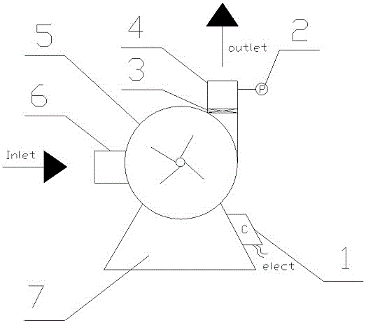
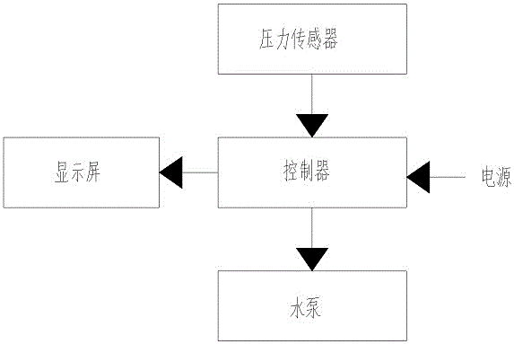
[0043] combine figure 1 and figure 2 A water pump shown includes a pump body 5, a water inlet 6, a water outlet 4, a base 7, a controller 1, a pressure sensor 2 and a check valve 3; wherein the water inlet 6 is the low pressure end of the water pump , the water outlet 4 is the high pressure end of the water pump, the water outlet 4 and the water inlet 6 are connected to the pump body; the pressure sensor 2 is used to detect the outlet pressure of the water pump, and output a pressure signal to the controller 1; The controller 1 is the control terminal of the water pump, which is used to connect the external power supply and control the start and stop of the water pump; the check valve 3 is arranged at the water outlet 4 and upstream of the pressure sensor 2 .
Embodiment 2
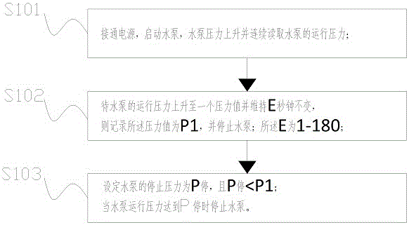
[0045] combine image 3 As shown, the water pump described in the above-mentioned embodiment 1 uses the water pump control method based on the pressure sensor to control the water pump, including the following steps,
[0046] S101, turn on the power, start the water pump, the pressure of the water pump rises and continuously read the operating pressure of the water pump;
[0047] S102, when the operating pressure of the water pump rises to a pressure value and maintains for E seconds and no longer rises, then record the pressure value as P1, and stop the water pump; the E is 1-180;
[0048] S103, set the stop pressure of the water pump as P 停 , and P 停 ≤P1; when the pump operating pressure reaches P 停 stop the water pump.
[0049] Further, combine Figure 4 As shown, the step S101 includes reading the starting pressure P of the water pump 启 ; and in the step S103, the P 停 >P 启 ; In the follow-up work, the water pump controls the start and stop of the water pump accordi...
Embodiment 3
[0062] combine Figure 8 The shown controller is a control circuit board using the pressure sensor-based water pump control method described in Embodiment 2; the control circuit board includes a single-chip microcomputer 11, a drive module 21, a circuit module 41 and a relay 31; wherein,
[0063] The single-chip microcomputer 11 is used to store data and execute software programs, receive pressure signals and output signals; specifically, it is used for timing, reading pressure signals and / or starting pressure, recording and calculating pressure signals, setting water pump stop pressure and / or Or start the pressure, control the driving module 21, and / or output the pressure signal;
[0064] The drive module 21 is connected with the single chip microcomputer 11, and is used to control the switch of the relay 31;
[0065] The relay 31 is used to control the power on and off of the water pump and is connected to the drive module 21;
[0066] The circuit module 41 is used to supp...
PUM
 Abstract
Description
Claims
Application Information
 - R&D
- Intellectual Property
- Life Sciences
- Materials
- Tech Scout
- Unparalleled Data Quality
- Higher Quality Content
- 60% Fewer Hallucinations
Browse by: Latest US Patents, China's latest patents, Technical Efficacy Thesaurus, Application Domain, Technology Topic, Popular Technical Reports.
© 2025 PatSnap. All rights reserved.Legal|Privacy policy|Modern Slavery Act Transparency Statement|Sitemap|About US| Contact US: help@patsnap.com


