
High-power LED lamp cooling device

A technology for LED lamps and heat sinks, which is applied to cooling/heating devices, lighting devices, components of lighting devices, etc. The problem of high junction temperature can achieve the effect of reasonable components and proportions, good heat dissipation effect and energy loss reduction.

Inactive Publication Date: 2016-12-07
中山市风华稀柠照明设计有限公司
View PDF10 Cites 8 Cited by
  • Summary
  • Abstract
  • Description
  • Claims
  • Application Information

AI Technical Summary

Problems solved by technology

[0002] At present, the high-power and high-brightness white LED light source has gradually replaced the traditional light source, but the problem of high junction temperature of the LED cannot be effectively solved, resulting in problems such as a decrease in the luminous efficiency of the LED chip, light decay, aging, and shortened service life. It cannot be used in the field of street lighting with high illuminance, harsh environment and long service life

Method used


Image

  • High-power LED lamp cooling device
  • High-power LED lamp cooling device
  • High-power LED lamp cooling device

Examples


Embodiment 2

[0036] The heat dissipation coating of the present invention comprises the following components by weight:

[0037] .

[0038] The heat dissipation coating of the present invention is prepared by the following method, comprising the steps of:

[0039] A, water-based acrylic resin, polycarbonate-type water-based polyurethane, silicone resin containing modified nanoparticles, silica sol and water are mixed and stirred evenly;

[0040] B. Add thermally conductive fillers and additives in the state of stirring, and stir evenly to obtain a dispersion system;

[0041] C. Put the dispersion system in step B into a paint grinder and grind it to 30-50 μm, and disperse evenly by ultrasonic.

[0042] Wherein said polycarbonate type waterborne polyurethane is prepared by the following method:

[0043] Add 1000 parts by weight of polycarbonate diol into a container with a stirrer, raise the temperature to 90°C, distill under reduced pressure for 0.5 hours, cool down to 70°C, add 280 p...

Embodiment 3

[0051] The heat dissipation coating of the present invention comprises the following components by weight:

[0052] .

[0053] The heat dissipation coating of the present invention is prepared by the following method, comprising the steps of:

[0054] A, water-based acrylic resin, polycarbonate-type water-based polyurethane, silicone resin containing modified nanoparticles, silica sol and water are mixed and stirred evenly;

[0055] B. Add thermally conductive fillers and additives in the state of stirring, and stir evenly to obtain a dispersion system;

[0056] C. Put the dispersion system in step B into a paint grinder and grind it to 30-50 μm, and disperse evenly by ultrasonic.

[0057] Wherein said polycarbonate type waterborne polyurethane is prepared by the following method:

[0058] Add 1000 parts by weight of polycarbonate diol into a container with a stirrer, raise the temperature to 90°C, distill under reduced pressure for 0.5 hours, cool down to 70°C, add 280 p...

Embodiment 4

[0066] The heat dissipation coating of the present invention comprises the following components by weight:

[0067] .

[0068] The heat dissipation coating of the present invention is prepared by the following method, comprising the steps of:

[0069] A, water-based acrylic resin, polycarbonate-type water-based polyurethane, silicone resin containing modified nanoparticles, silica sol and water are mixed and stirred evenly;

[0070] B. Add thermally conductive fillers and additives in the state of stirring, and stir evenly to obtain a dispersion system;

[0071] C. Put the dispersion system in step B into a paint grinder and grind it to 30-50 μm, and disperse evenly by ultrasonic.

[0072] Wherein said polycarbonate type waterborne polyurethane is prepared by the following method:

[0073] Add 1000 parts by weight of polycarbonate diol into a container with a stirrer, raise the temperature to 90°C, distill under reduced pressure for 0.5 hours, cool down to 70°C, add 280 p...


PUM


Abstract

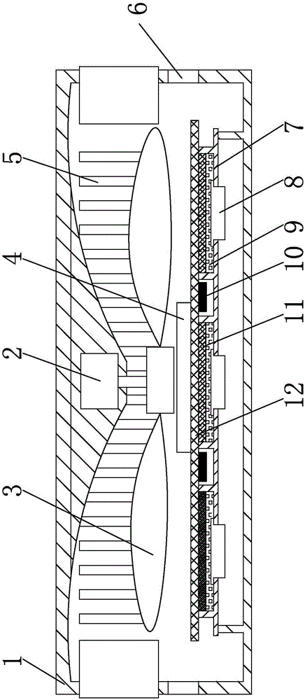
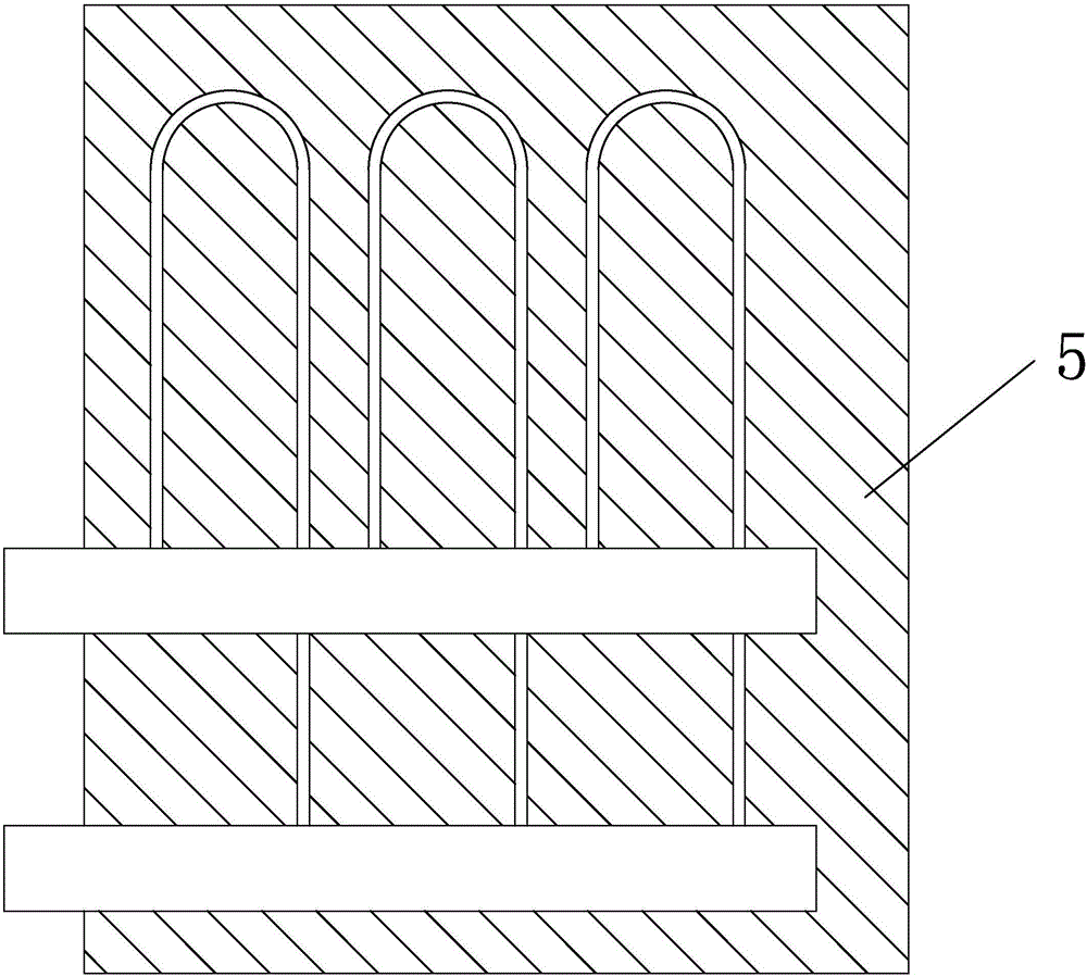
The invention discloses a high-power LED lamp cooling device which comprises a mounting substrate. Mounting seats are arranged on the surface of the mounting substrate. A light source chip is mounted inside each mounting seat in a matched mode, and graphite plates are arranged on the light source chips and fixedly connected with a capillary pipe heat absorbing plate. The mounting substrate is fixedly connected with a bottom surface support inside a lampshade, and a motor is additionally mounted at the top end of the interior of the lampshade. Turbine blades are additionally mounted at the shaft end of the motor. Cooling grid plates are evenly mounted at the upper end of the side edge of the lampshade, cooling grids are arranged on the positions, below the cooling grid plates, of the surface of the lampshade, and the cooling grid plates and the capillary pipe heat absorbing plate are connected with a cooling liquid circulating device through guiding pipes. The cooling liquid circulating device and the motor are connected with a controller through wires. The novel high-power LED lamp cooling device has the multi-gear cooling capacity, an automatic control mode is adopted, and equipment energy consumption is greatly lowered on the premise of guaranteeing the cooling capacity.

Description

technical field [0001] The invention relates to the technical field of heat dissipation of electronic components, in particular to a heat dissipation device for high-power LED lamps. Background technique [0002] At present, the high-power and high-brightness white LED light source has gradually replaced the traditional light source, but the problem of high junction temperature of the LED cannot be effectively solved, resulting in problems such as a decrease in the luminous efficiency of the LED chip, light decay, aging, and shortened service life. It cannot be used in the field of street lighting with high illuminance, harsh use environment and long service life. With the needs of LED green lighting and energy-saving situation, the development of high-brightness, high-power LED light source lamps suitable for street lighting has become a new topic. Therefore, we propose a high-power LED lamp heat sink. Contents of the invention [0003] The purpose of the present inventi...

Claims


Application Information

Patent Timeline
Patent Type & Authority Applications(China)
IPC IPC(8): F21K9/20F21V29/58F21V29/67F21V29/76F21V29/83F21V29/87F21V23/00C09D133/00C09D175/04C09D183/04C09D7/12F21Y115/10
CPCF21V29/58C08K2201/011C08L2205/03C09D7/61C09D7/70C09D133/00F21V23/003F21V29/67F21V29/76F21V29/83F21V29/87C08L75/04C08L83/04C08K13/06C08K9/02C08K7/24C08K3/36C08K2003/0812C08K2003/0862C08K2003/0806C08K3/28C08K2003/282
Inventor 郭月强
Owner 中山市风华稀柠照明设计有限公司
Learn More