Wavelength conversion device, light emitting device and projecting device

A wavelength conversion device and light-emitting layer technology, which is applied in the field of laser display technology and lighting, can solve the problems of heat accumulation in the light-emitting layer, long heat propagation path, and reduced conversion efficiency, so as to reduce heat, shorten heat propagation distance, and avoid heat. Effect

Inactive Publication Date: 2016-12-07
APPOTRONICS CORP LTD
View PDF7 Cites 19 Cited by
  • Summary
  • Abstract
  • Description
  • Claims
  • Application Information

AI Technical Summary

Problems solved by technology

[0005] However, since the heat generated by the glass light-emitting layer needs to pass through the glass light-emitting layer and the inorganic reflective layer to reach the heat-conducting substrate before it can be dissipated. The phosphor powder works at high temperature for a long time and the conversion efficiency decreases

Method used


Image

  • Wavelength conversion device, light emitting device and projecting device
  • Wavelength conversion device, light emitting device and projecting device
  • Wavelength conversion device, light emitting device and projecting device

Examples


Embodiment 1

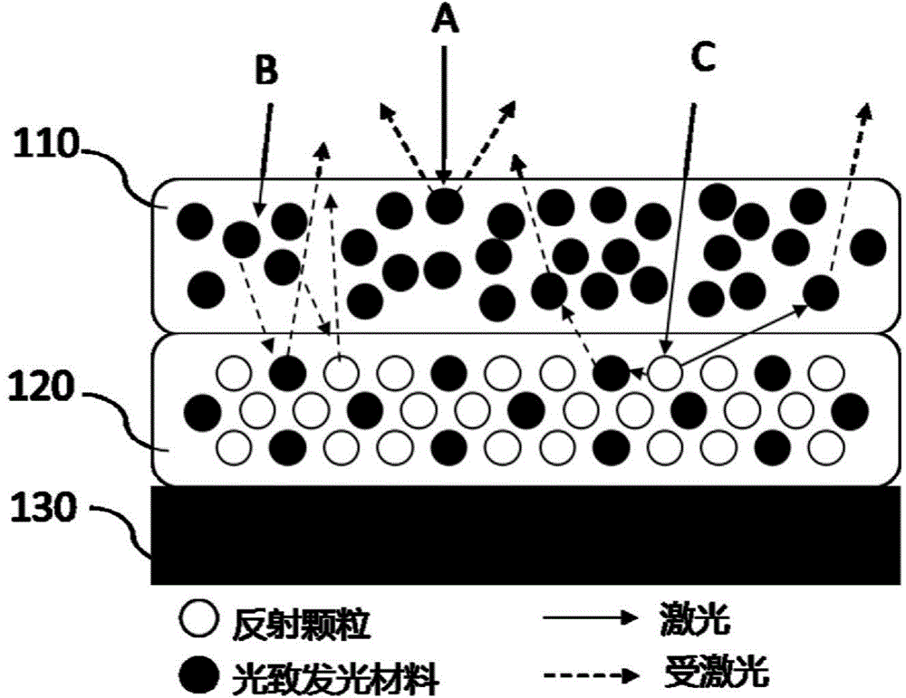
[0032] See figure 1 , figure 1 It is a schematic structural diagram of a wavelength conversion device according to Embodiment 1 of the present invention. The wavelength conversion device includes a light emitting layer 110 , a reflective layer 120 and a thermally conductive substrate 130 .

[0033] The light emitting layer 110 includes a first photoluminescent material and a first adhesive. The black solid balls in the luminescent layer 110 in the figure represent phosphor particles of the first photoluminescent material, which may be any one of yellow phosphor, green phosphor, orange phosphor, and red phosphor. The first photoluminescent material is encapsulated into a layer by the first adhesive, and distributed uniformly or substantially uniformly in the continuum formed by the first adhesive. The first binder in the present invention is an inorganic binder, specifically, the inorganic binder is a first glass frit. In a preferred embodiment of the present invention, the ...

Embodiment 2

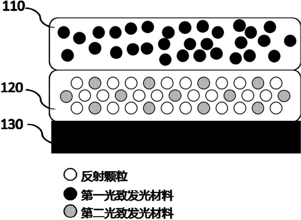
[0049] See image 3 , image 3 It is a schematic structural diagram of the wavelength conversion device of Embodiment 2 of the present invention. The difference between this embodiment and Embodiment 1 is only that the second photoluminescent material in the reflective layer 120 (shown by the hatched ball in the figure) is in contact with the light emitting material. The first photoluminescent material in the layer 110 (the black solid ball in the figure) is different, and the light emitted by the first photoluminescent material can excite the second photoluminescent material and emit light with a longer wavelength.

[0050] After the first photoluminescent material is excited by the excitation light, the energy of the emitted light is reduced and the wavelength becomes longer. The heat generated by the second photoluminescent material excited by the light is much larger than that of the second photoluminescent material directly excited by the excitation light. reduce. Among...

Embodiment 3

[0054] Such as Figure 4 Shown is a schematic structural view of the color wheel in Embodiment 3 of the present invention, 4a is a cross-sectional view of the color wheel, and 4b is a top view of the color wheel. The color wheel is a circular color wheel, including a light emitting layer 110 , a reflective layer 120 and a ceramic substrate 130 . The structural composition of the light emitting layer 110 , the reflective layer 120 and the ceramic substrate 130 can refer to the description of the wavelength conversion device in the first and second embodiments above.

[0055] In this embodiment, the luminous layer 110, the reflective layer 120 and the ceramic substrate 130 are all annular structures, and in a modified embodiment of the present invention, the luminescent layer 110, the reflective layer 120 and the ceramic substrate 130 can be solid circular layer structure. The light-emitting layer 110 and the reflective layer 120 may each have a fan-ring structure, for example...


PUM


Abstract

The invention relates to a wavelength conversion device, a light emitting device which comprises the wavelength conversion device and a projecting device comprising the wavelength conversion device. The wavelength conversion device comprises a light emitting layer and a reflecting layer which are arranged in a stacked manner. The light emitting layer comprises a first photoluminescence material and a first adhesive. The reflecting layer comprises a second photoluminescence material, a second adhesive and reflecting particles. Light emitted from the reflecting layer completely exits through the light emitting layer, and the light emitting layer and the reflecting layer are directly connected or connected through a sintering layer. On one hand, heat generated by the second photoluminescence material only needs to penetrate a part of the reflecting layer to be emitted, the heat spread distance is shortened, and meanwhile the reflecting capacity of the reflecting layer is retained; and on the other hand, the heat generated by the second photoluminescence material is reduced, the wavelength conversion device can work at a low temperature, and therefore the better light emitting efficiency is achieved.

Description

technical field [0001] The invention relates to the field of laser display technology and lighting, in particular to a wavelength conversion device, a light emitting device and a projection device. Background technique [0002] With the development of display and lighting technology, the original halogen bulb as a light source is increasingly unable to meet the high power and high brightness requirements of display and lighting. Visible light of various colors can be obtained by using excitation light emitted by a solid-state light source such as LD (Laser Diode, laser diode) to excite wavelength conversion materials, and this technology is increasingly used in lighting and display. This technology has the advantages of high efficiency, low energy consumption, low cost, and long life, and is an ideal alternative to existing white or monochromatic light sources. [0003] In the prior art, the laser light source is used to irradiate the wavelength conversion device to obtain ...

Claims


Application Information

Patent Timeline
Patent Type & Authority Applications(China)
IPC IPC(8): F21V9/16
CPCH01S5/06F21V9/38
Inventor 李乾许颜正
Owner APPOTRONICS CORP LTD
Why Eureka
Try Eureka