A coaxial gas discharge vacuum ultraviolet light source device
A vacuum ultraviolet light source and gas discharge technology, applied in the direction of gas plasma lamps, lamp parts, etc., can solve the problems of low output light power and low photon utilization rate, achieve high effective vacuum ultraviolet light power, increase effective area, The effect of improving the purity
- Summary
- Abstract
- Description
- Claims
- Application Information
AI Technical Summary
Problems solved by technology
Method used
Image
Examples
specific Embodiment approach 1
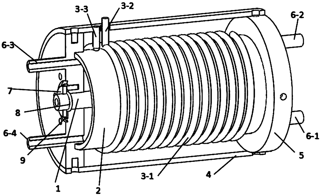
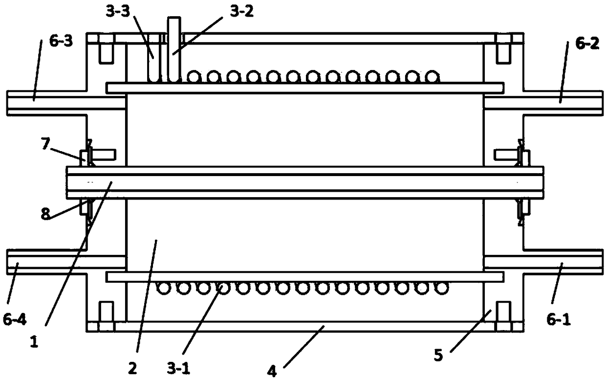
[0017] Specific implementation mode one: combine figure 1 To illustrate this embodiment, the overall structure of the coaxial gas discharge vacuum ultraviolet light source device described in this embodiment includes a central cylindrical interaction cavity, a coaxial annular discharge light source cavity, a radio frequency spiral resonance excitation cavity and an ultra-high vacuum flange connector. part. The specific implementation steps are as follows: firstly, the solenoid coil is sleeved on the outside of the quartz glass tube 2, and bonded in the installation groove of the flange connector 5 with an adhesive that can be used in an ultra-high vacuum environment, so as to realize the connection between the outer wall of the discharge light source cavity and the atmosphere. The length of the quartz glass tube determines the overall length reference of the entire device; secondly, the copper shielding layer 4 is installed on the outside of the coil in a coaxial manner, and t...
specific Embodiment approach 2
[0018] Specific embodiment two: this embodiment is a further limitation of the coaxial gas discharge vacuum ultraviolet light source device described in embodiment one, combined with figure 1 This embodiment will be described. In this embodiment, the gas conduits on the flange connector 5 can be increased or decreased as required. By adjusting the switch mode of the gas conduits, switching between different working states of flowing gas and non-flowing gas can be realized: the working gas in the flowing state has an inlet, There is also an outlet. When the vacuum ultraviolet lamp is working, the gas is in a dynamic balance in the discharge light source cavity; according to the way of air intake and outlet, it can also be divided into forward flow (gas flows in from 6-1 and flows out from 6-3) and countercurrent (gas flows from 6-3) 1 inflow, flow out from 6-2) two states. When working in a non-flowing state, the gas is sealed inside the cavity of the discharge light source an...
specific Embodiment approach 3
[0019] Embodiment 3: This embodiment is a further limitation of the coaxial gas discharge vacuum ultraviolet light source device described in Embodiment 1. In this embodiment, helium can be filled into the cavity of the discharge light source through the gas conduit according to the needs of practical applications. , neon, argon, krypton, xenon and other different working gases or mixed gases to generate vacuum ultraviolet light with different wavelengths; by adjusting the gas pressure in the discharge light source cavity and the frequency and power of the RF signal in the spiral resonant cavity, etc., you can Adjust the output power of vacuum ultraviolet light to meet the needs of different applications for light sources.
PUM
 Abstract
Description
Claims
Application Information
 - R&D
- Intellectual Property
- Life Sciences
- Materials
- Tech Scout
- Unparalleled Data Quality
- Higher Quality Content
- 60% Fewer Hallucinations
Browse by: Latest US Patents, China's latest patents, Technical Efficacy Thesaurus, Application Domain, Technology Topic, Popular Technical Reports.
© 2025 PatSnap. All rights reserved.Legal|Privacy policy|Modern Slavery Act Transparency Statement|Sitemap|About US| Contact US: help@patsnap.com


