
Multisource fluid waste heat recycling system

A waste heat recovery and thermal system technology, applied in the direction of fluid heaters, heat pumps, heat storage equipment, etc., can solve the problems of insufficient waste heat storage, unable to meet the waste heat utilization of workshops, unable to recover various heat sources of different properties, and unable to fully store waste heat, etc. , to achieve the effect of reducing cleaning and maintenance times, ensuring recycling and utilization, and ensuring full utilization

Inactive Publication Date: 2016-12-07
DALIAN JIAOTONG UNIVERSITY
View PDF4 Cites 12 Cited by
  • Summary
  • Abstract
  • Description
  • Claims
  • Application Information

AI Technical Summary

Problems solved by technology

[0002] In order to save energy and reduce production costs, most manufacturers will build waste heat recovery and utilization systems to recover and utilize the heat generated in the production process, but most of the existing waste heat recovery systems are single heat source recovery and utilization systems, which cannot Recover a variety of heat sources with different properties and use them
When there is too much waste heat in the peak production period of the workshop, it is impossible to fully store too much waste heat; when the production of the workshop is low, the storage of waste heat is not enough to meet the utilization of waste heat in the workshop
If multiple waste heat recovery systems are built, it will undoubtedly increase the investment of the manufacturer, and if there is too much waste heat in the workshop, it is necessary to build a cooling tower to dissipate the waste heat, increasing unnecessary capital investment, and the efficiency of recycling is not high

Method used


Image

  • Multisource fluid waste heat recycling system
  • Multisource fluid waste heat recycling system

Examples


Embodiment Construction

[0029] The present invention will be further described below in conjunction with the accompanying drawings.

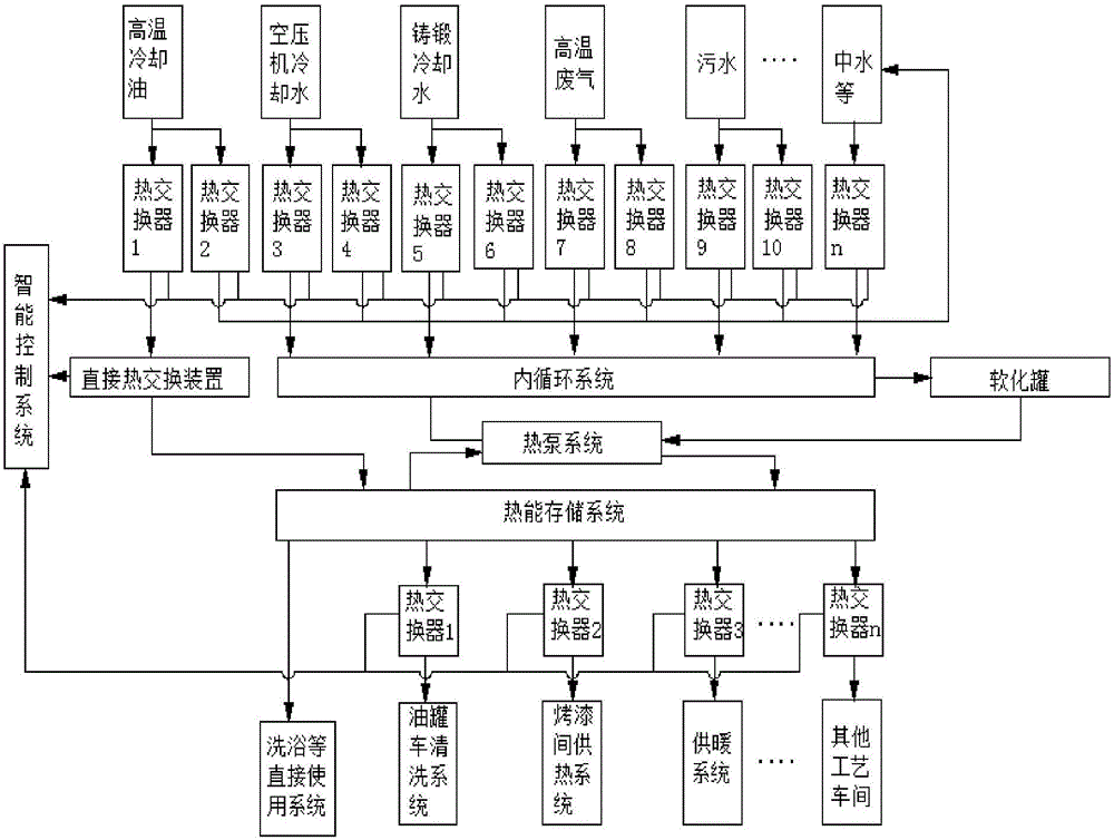
[0030] A multi-source waste heat recovery system such as figure 1As shown, from the perspective of the system, it is divided into heat source system, multi-heat source and heat exchange system of heat source internal circulation system of heat pump, softening tank water treatment system, high-efficiency heat exchange and heat pump system, heat storage hot water system, multi-purpose heat Exchange system and hot water delivery system, etc. Each system unit is a separate internal cycle, and the water in each unit does not touch each other, and the heat is directly transferred to another cycle through heat exchange. High-temperature flue gas and high-temperature cooling oil pass through heat exchangers and direct heat exchange devices to obtain higher-temperature water directly transfer heat to the water tank of the thermal energy storage system or use other cooling wate...


PUM


Abstract

The invention discloses a multisource waste heat recycling system. The multisource waste heat recycling system comprises a heat source system, a heat source end heat exchange system, a softening tank water treatment system, a heat pump system, a heat storage hot water system, a multipurpose heat exchange system, a heat application system and an intelligent control system. According to the multisource waste heat recycling system, an independent inner circulating system is arranged, thus, the heat pump heat source end temperature can be ensured, meanwhile, dirt and impurities in water can be prevented from making contact with each other, separate softening treatment can be conducted on circulating water, and the heat source end water quality is ensured; in addition, mutual contact between the heat pump system and liquid with different components is isolated through the inner circulating system, the cleaning times and the maintenance times are decreased, and hence the stability and the reliability of operation of the heat pump system are ensured; a middle pool is arranged for energy storage, during the production peak, excess heat is recycled to the middle pool, and during the production trough, the middle pool is opened, and heat energy is transmitted into a heat energy storage system so that the requirement of a workshop can be met; and the middle pool is adopted for energy storage, so that the cost is reduced, and meanwhile, the excess heat is further collected.

Description

technical field [0001] The invention relates to waste heat recovery and utilization technology, in particular to a multi-source fluid waste heat recovery and utilization system. Background technique [0002] In order to save energy and reduce production costs, most manufacturers will build waste heat recovery and utilization systems to recover and utilize the heat generated in the production process, but most of the existing waste heat recovery systems are single heat source recovery and utilization systems, which cannot A variety of heat sources with different properties are recovered and utilized. When there is too much waste heat in the peak production period of the workshop, it is impossible to fully store too much waste heat. When the production of the workshop is low, the storage of waste heat is not enough to meet the utilization of waste heat in the workshop. Building multiple waste heat recovery systems will undoubtedly increase the investment of the manufacturer, ...

Claims


Application Information

Patent Timeline
IPC IPC(8): F28D20/00F28F27/02F25B30/06F24H4/02
CPCF24H4/02F25B30/06F28D20/0034F28F27/02Y02E60/14
Inventor 谭晓东孔令昊白杰汤浩秦来超
Owner DALIAN JIAOTONG UNIVERSITY
Learn More