
Optical waveguide plate and optical fiber coupling connection method, optical waveguide plate and communication transmission system

An optical fiber coupling and connection method technology, which is applied to the optical waveguide light guide, the coupling of the optical waveguide, the light guide, etc., can solve the problems of poor alignment between the optical waveguide plate and the fiber, poor transmission stability, etc. Accuracy and the effect of improving core competitiveness

Active Publication Date: 2016-12-07
ZTE CORP
View PDF3 Cites 9 Cited by
  • Summary
  • Abstract
  • Description
  • Claims
  • Application Information

AI Technical Summary

Problems solved by technology

[0005] The main technical problem to be solved by the present invention is to provide a method for coupling and connecting an optical waveguide plate and an optical fiber, an optical waveguide plate and a communication transmission system to solve the problem of misalignment between the optical waveguide plate and the optical fiber in the prior art, which in turn leads to transmission during communication transmission. The problem of poor stability

Method used


Image

  • Optical waveguide plate and optical fiber coupling connection method, optical waveguide plate and communication transmission system
  • Optical waveguide plate and optical fiber coupling connection method, optical waveguide plate and communication transmission system
  • Optical waveguide plate and optical fiber coupling connection method, optical waveguide plate and communication transmission system

Examples


Embodiment 1

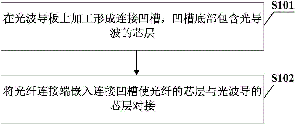
[0040] The optical waveguide plate and the optical fiber coupling connection method of this embodiment, such as figure 1 shown, including the following steps:

[0041] Step S101: Processing and forming a connecting groove on the optical waveguide plate, the bottom of the groove contains the core layer of the optical waveguide;

[0042] In this step, the optical waveguide board refers to a printed circuit board with an optical waveguide transmission layer, and it should be understood that various existing circuit boards containing an optical waveguide transmission layer are included. Process the existing optical waveguide plate, that is, process the core layer and the surrounding core layer of the optical waveguide plate to form a connection groove. The core layer of the optical fiber and the core layer of the optical waveguide are butted during the groove. Further, in order to facilitate the accuracy of butt joint between the core layer of the optical fiber and the core laye...

Embodiment 2

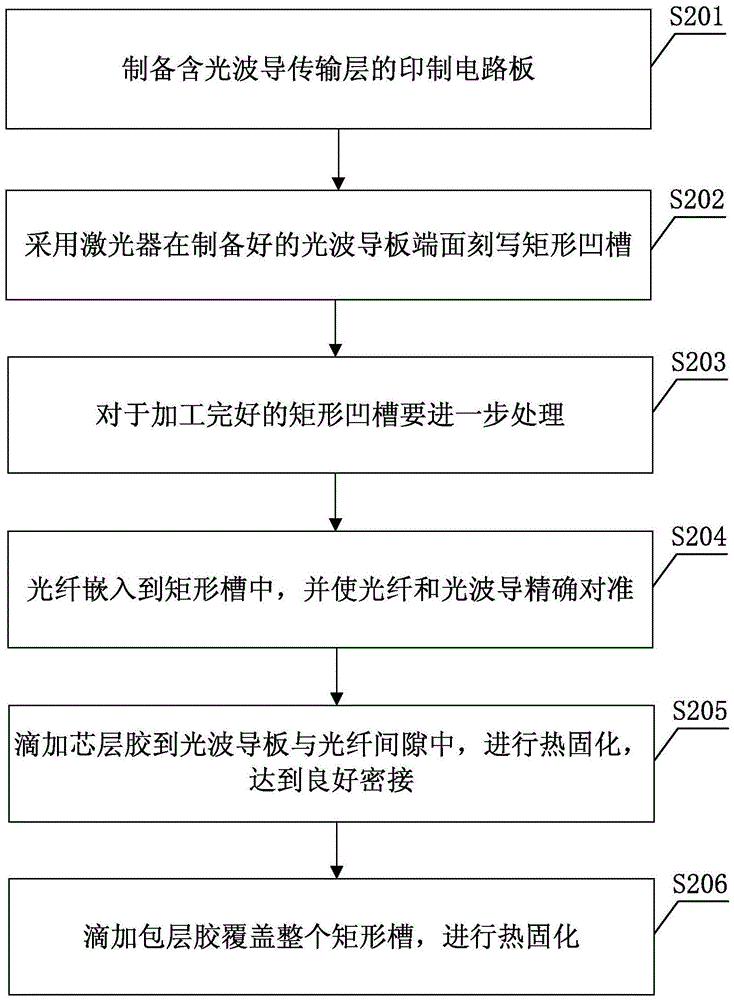
[0052] The coupling connection method between the optical waveguide plate and the optical fiber of the present embodiment of the present embodiment, the method in this example is specifically as follows figure 2 shown, including the following steps:

[0053] Step S201: preparing a printed circuit board containing an optical waveguide transmission layer, that is, an optical waveguide plate;

[0054] In this step, the prepared optical waveguide plate in this step has a core layer size of 50 μm x 50 μm, and an upper cladding layer and a lower cladding layer thickness of 50 μm, or the core layer, upper cladding layer, and lower cladding layer size of the optical waveguide are not limited to above dimensions.

[0055] Step S202: Using a laser to write a rectangular groove on the end surface of the prepared optical waveguide plate;

[0056] In this step, specific parameters such as exposure energy, dot frequency, and stepping speed can be set on the working software of the laser,...

Embodiment 3

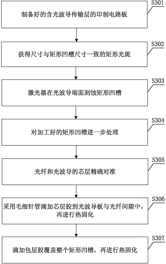
[0067] The coupling connection method between the optical waveguide plate and the optical fiber in this embodiment of this embodiment mainly uses a laser to etch a rectangular groove on the end face of the prepared optical waveguide. The rectangular groove is a kind of connection groove, and the specific shape can be Depending on the specific situation, the optical fiber is embedded in the rectangular groove to realize the butt coupling, and finally the waveguide glue is used for curing and packaging to realize the parallel coupling of the optical waveguide and the optical fiber. This method cleverly applies the micromachining technology to the parallel coupling technology of the optical waveguide plate and the optical fiber, overcomes the alignment deviation of the optical waveguide-fiber connection caused by external forces such as vibration and collision, and avoids the long-term exposure of the connector to the optical fiber. In the air, its end face is susceptible to dust ...


PUM


Abstract

The invention provides an optical waveguide plate and optical fiber coupling connection method an optical waveguide plate and a communication transmission system, which belongs to a communication system. The optical waveguide plate is processed to form a connection groove. The bottom of the groove comprises the core layer of optical waveguide. An optical fiber connection end is embedded into the connection groove, and an optical fiber core layer and the optical waveguide core layer are in butt joint. Compared with the prior art, the connection method, the optical waveguide plate and the communication transmission system have the advantages that the method that a guide pin is inserted into grooves on both sides of an optical waveguide plate core layer to realize the butt joint of the optical fiber core layer and the optical waveguide core layer is eliminated; the optical waveguide plate is processed to form the connection groove; the groove directly accommodates the optical fiber connection end, so that the optical fiber core layer and the optical waveguide plate core layer are in direct butt joint; accurate alignment and connection are realized; the impact of vibration, collision and other environmental forces is avoided; the alignment accuracy of the optical fiber core layer and the optical waveguide plate core layer is improved; the transmission stability of communication transmission is improved; the optical fiber connection end does not need a guide pin; the optical fiber connection end is simply processed; and the core competitiveness of a product is improved.

Description

technical field [0001] The invention relates to the communication field, in particular to a method for coupling and connecting an optical waveguide plate and an optical fiber, an optical waveguide plate and a communication transmission system. Background technique [0002] The rapid development of broadband communications, supercomputers and big data centers has continuously promoted the rapid growth of information transmission bandwidth. The limitations of traditional electrical interconnection technologies in terms of bandwidth, distance, and energy consumption have become more and more prominent. The transmission bandwidth of 10Gbps Electrical interconnection technology can only realize information transmission at a distance of 0.3m to 1m, but it is helpless for high-speed interconnections such as 25Gbps and 40Gbps. In recent years, the optical printed backplane interconnection technology based on the optical waveguide theory has gradually developed, and has been widely s...

Claims


Application Information

Patent Timeline
Patent Type & Authority Applications(China)
IPC IPC(8): G02B6/24
CPCG02B6/122G02B6/13G02B6/30
Inventor 赵丽庞拂飞王廷云邓传鲁朱涛贾娜娜王玉刘哲
Owner ZTE CORP
Learn More