Reflective display device and manufacturing method thereof

A reflective display and manufacturing method technology, applied in nonlinear optics, instruments, optics, etc., can solve the problem of low light transmittance, achieve the effect of reducing loss and improving light transmittance

Inactive Publication Date: 2016-12-07
BOE TECH GRP CO LTD
View PDF6 Cites 17 Cited by
  • Summary
  • Abstract
  • Description
  • Claims
  • Application Information

AI Technical Summary

Problems solved by technology

[0007] Embodiments of the present invention provide a reflective display device and a manufacturing method thereof, which are used to solve the problem of light trans

Method used


Image

  • Reflective display device and manufacturing method thereof
  • Reflective display device and manufacturing method thereof
  • Reflective display device and manufacturing method thereof

Examples


Embodiment 1

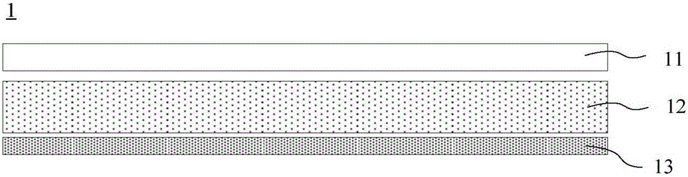
[0043] Such as figure 2 As shown, the embodiment of the present invention provides a reflective display device 1, including: a circular polarizer 11, a liquid crystal (Liquid Crystal, abbreviated as LC) layer 12, and a cholesteric liquid crystal (abbreviated as CLC) Layer 13.

[0044] Among them, the circular polarizer 11 can convert external light into circularly polarized light, where it can be converted into left-handed circularly polarized light and right-handed circularly polarized light.

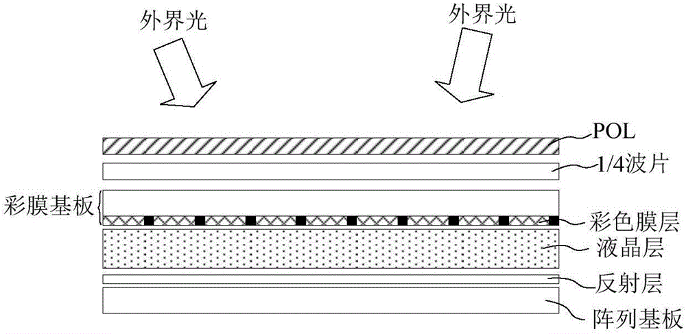
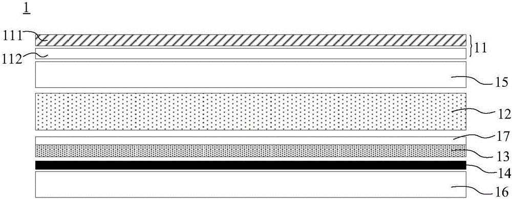
[0045] Preferably, such as image 3 As shown, the circular polarizer 11 may include: a linear polarizer 111 and a quarter wave plate 112 located below the linear polarizer 111, wherein the optical axis of the quarter wave plate 112 is transparent to the linear polarizer 111. The axis is 45 degrees. The external light may pass through the linear polarizer 111 and then become linearly polarized light, and the linearly polarized light may become circularly polarized light after passing throu...

Embodiment 2

[0080] reference Picture 9 The embodiment of the present invention provides a manufacturing method of a reflective display device, including:

[0081] S101, forming a cholesteric liquid crystal layer on the second substrate.

[0082] Wherein, the cholesteric liquid crystal layer is used to reflect left-handed circularly polarized light without reflecting right-handed circularly polarized light, or used to reflect right-handed circularly polarized light without reflecting left-handed circularly polarized light, wherein, the cholesteric liquid crystal The layer is divided into a plurality of reflecting units, each of the reflecting units includes a plurality of reflecting subunits, and the pitch of the cholesteric liquid crystal in different reflecting subunits is different.

[0083] Preferably, this step may include:

[0084] Firstly, a barrier wall is made on the second substrate with an opaque material to separate multiple accommodating cavities. Among them, the opaque material ma...


PUM


Abstract

The embodiment of the invention discloses a reflective display device and a manufacturing method thereof and relates to the technical field of display. The device aims to solve the problem of existing reflective liquid crystal display devices that light transmittance is low due to luminous energy consumption when light permeates through a color filter. The device comprises a round polaroid, a liquid crystal layer located under the round polaroid and used for controlling light coming out of the round polaroid to be left rotation circularly polarized light or right rotation circularly polarized light, and a cholesteric phase liquid crystal layer located under the liquid crystal layer and used for reflecting left rotation circularly polarized light and not reflecting right rotation circularly polarized light, or reflecting right rotation circularly polarized light and not reflecting left rotation circularly polarized light, wherein the cholesteric phase liquid crystal layer comprises multiple reflection units, each reflection unit comprises multiple reflection subunits, and the screw pitches of cholesteric phase liquid crystal in different reflection subunits are different.

Description

Technical field [0001] The present invention relates to the field of display technology, in particular to a reflective display device and a manufacturing method thereof. Background technique [0002] In recent years, with the continuous advancement of science and technology and the continuous improvement of liquid crystal display technology, liquid crystal display products (for example, liquid crystal display LCD, the full English name is Liquid Crystal Display) have gradually spread in every corner of our lives. Among them, the reflective liquid crystal display has good outdoor readability and low power consumption, which has attracted people's attention. [0003] figure 1 The schematic diagram showing the structure of the core components of the reflective liquid crystal display provided by the prior art is shown. The reflective liquid crystal display includes: a polarizer (Polarizer, POL), a quarter wave plate, a color film substrate, a liquid crystal layer, a reflective layer a...

Claims


Application Information

Patent Timeline
IPC IPC(8): G02F1/1335G02F1/1347
CPCG02F1/133514G02F1/133553G02F1/1347G02F1/13478
Inventor 谷新张笑
Owner BOE TECH GRP CO LTD
Why Eureka
Try Eureka