Improved tunable dual-band bandpass filter

A band-pass filter, dual-band technology, used in resonators, waveguide-type devices, circuits, etc., can solve problems such as the cost of elliptical rods, the tuning mechanism that cannot be installed above the filter, and the rise

Active Publication Date: 2019-08-27
UNIVERSITY OF YAMANASHI +1
View PDF8 Cites 0 Cited by
  • Summary
  • Abstract
  • Description
  • Claims
  • Application Information

AI Technical Summary

Problems solved by technology

In such a case, if the rod 25 is formed in an elliptical shape, in order to increase the variation of the resonance in odd modes, then there will be a need for a mechanism capable of raising and lowering the rod 25 without rotating it, so the tuning mechanism will be greatly complicated , resulting in an increase in size
In this case, there is a possibility that the tuning mechanism itself cannot be mounted above the filter, causing the use of elliptical shaped rods 25 to be impractical from a cost point of view

Method used


Image

  • Improved tunable dual-band bandpass filter
  • Improved tunable dual-band bandpass filter
  • Improved tunable dual-band bandpass filter

Examples


Embodiment 1

[0067] For one embodiment of the resonator according to the invention, a microstrip line structure is used, but it should be pointed out that the invention is not limited thereto.

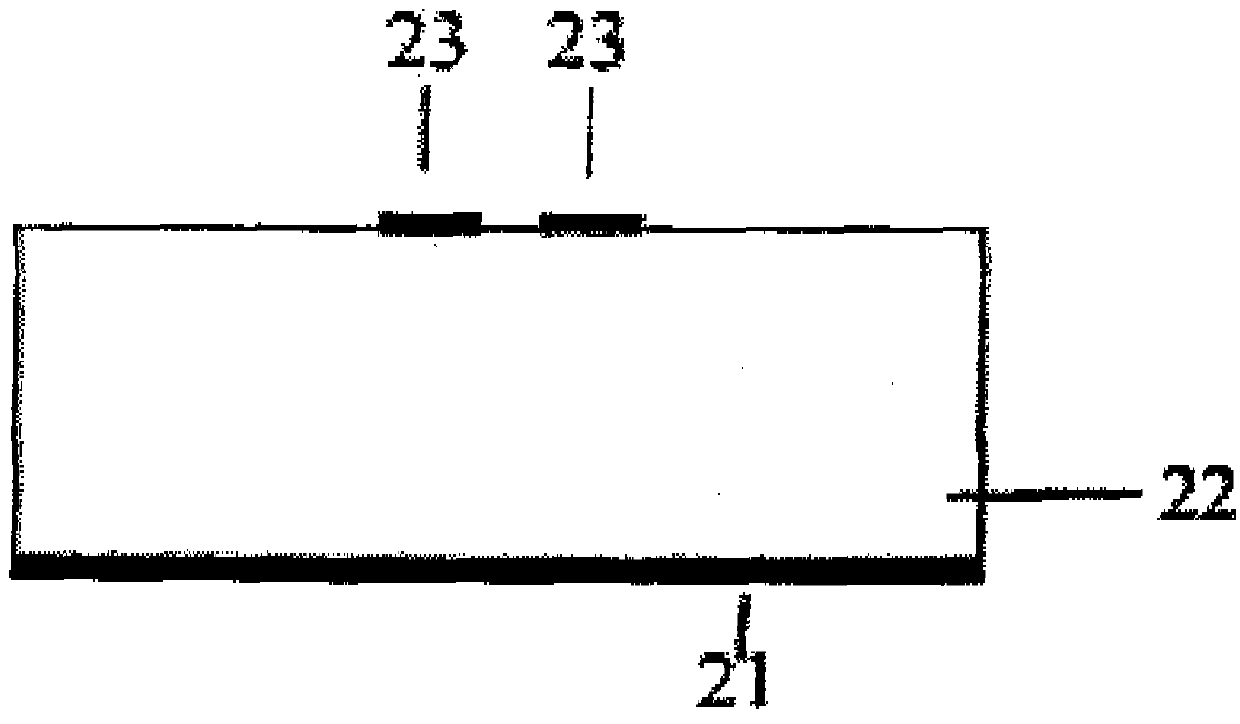
[0068] For the present invention, the microstrip line structure is adopted, and the appearance of the resonator as a whole is as figure 2 shown in . More specifically, a strip conductor 23 (corresponding to the half-wavelength resonator 10, the stub 11, the waveguide 12, and the feed wire 13, etc.) is provided on the upper portion of the dielectric body 22, and the ground conductor 21 is provided on the dielectric body 22 below. In order to control dielectric loss, the dielectric body 22 is preferably formed by using a material with a small dielectric loss tangent. In addition, in order to control temperature rise, the dielectric body 22 is preferably formed by using a material with high thermal conductivity. The ground conductor 21 is preferably formed by using a low conductive loss material, ...

Embodiment 2

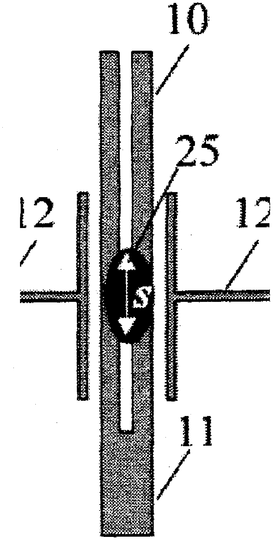
[0081] Figure 8 A tunable dual-band bandpass filter constructed by combining the tunable dual-band resonator resistors of the present invention into two stages is shown. Shown by 12 is a waveguide, and for inputting signals to or outputting signals from the tunable dual-band bandpass filter, a feed conductor 13 is arranged along the half-wavelength resonator 10 on the left-hand side . For signal output, a feed line 13 is arranged along the half-wavelength resonator 10 on the right-hand side. While the dielectric rod 25 is provided in the space above each of the half-wavelength resonator protrusions (capacity component adjustment parts) 10-a, 10-b, and the dielectric rod 25 is provided in the space above each corresponding stub 11 space, but they are not Figure 8 shown in .

Embodiment 3

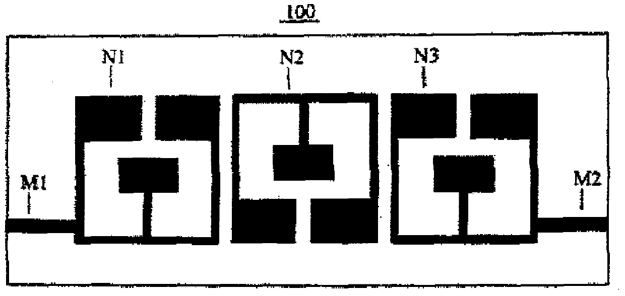
[0083] Figure 9 A tunable dual-band bandpass filter constructed by combining the tunable dual-band resistors of the present invention into three stages is shown. Shown by 12 is a waveguide, and for inputting signals to or outputting signals from the tunable dual-band bandpass filter, a feed conductor 13 is arranged along the half-wavelength resonator 10 on the left-hand side . For signal output, a feed line 13 is arranged along the half-wavelength resonator 10 on the right-hand side. exist Figure 9 The dielectric rod 25 disposed in the space above each of the half-wavelength resonator protrusions (capacity component adjustment portion) 10-a, 10-b and the space disposed above each corresponding stub 11 are not shown in The inner dielectric rod 25.


PUM


Abstract

To provide a tunable dual-band resonator capable of independently tuning the center frequency, and a tunable dual-band band-pass filter using the resonator. A dual-band resonator is structured such that a stub 11 is added to each half-wavelength resonator 10 provided with half-wavelength resonator protrusions (capacity-component adjust parts) 10-a, 10-b. A tunable dual-band resonator capable of tuning resonance frequencies in an even-number mode and an odd-number mode independently is configured by providing a dielectric rod circular in cross section in the space above the half-wavelength resonator protrusions (capacity-component adjust parts) 10-a, 10-b. Each half-wavelength resonator 10 is formed of one thin strip conductor with a deeply retreated groove having a width g. A tunable dual-band band-pass filter is configured by arranging a plurality of the tunable dual-band resonators.

Description

technical field [0001] The present invention relates to frequency tuning and improvement (adjustment) of band-pass characteristics of devices using high-frequency waves and microwaves for signal transmission / reception in the field of communication technology including, for example, mobile communication, satellite communication, fixed microwave communication, etc., namely , a tunable dual-band bandpass filter. Background technique [0002] Data communication for video and the like have recently undergone a huge explosion in use, so that a network capacity crisis and a frequency resource crisis are expected to cause major problems on a global scale. In order to deal with this situation, the development of microwave filters used by base stations of mobile communication is required in order to simultaneously realize high-speed / large-capacity communication and efficient use of frequency resources. In addition, communication devices capable of handling multiple frequency bands ar...

Claims


Application Information

Patent Timeline
Patent Type & Authority Patents(China)
IPC IPC(8): H01P1/203H01P7/08
CPCH01P1/20372
Inventor 关谷尚人寺尾胜广岸田和人佐藤庸夫北田典敬
Owner UNIVERSITY OF YAMANASHI
Why Eureka
Try Eureka