Outer-tooth and inner-stator structure of motor and manufacturing method of outer-tooth and inner-stator structure

A manufacturing method and technology of inner stator, applied in the manufacture of stator/rotor body, magnetic circuit shape/style/structure, magnetic circuit static parts, etc., can solve the problem of low slot full rate, insufficient slot width, waste, etc. problem, to achieve the effect of simple manufacturing method, low manufacturing cost and tightness guarantee

Inactive Publication Date: 2016-12-07
PHASE IND DESIGN NINGBO
View PDF5 Cites 3 Cited by
  • Summary
  • Abstract
  • Description
  • Claims
  • Application Information

AI Technical Summary

Problems solved by technology

[0002] Whether it is a permanent magnet brushless DC motor driven by a square wave or a permanent magnet AC servo motor driven by a sine wave, the structure of the motor body is basically the same or similar. According to the position of the fixed parts, it is divided into inner stator or outer stator, inner stator The winding teeth on the outer stator are arranged on the outer side, and the corresponding rotor is also on the outer side, while the winding teeth on the outer stator are arranged on the inner side, and the corresponding rotor is also arranged on the inner side, whether it is an inner stator or an outer stator, They are all ring-shaped structures. The existing stators are all stamped and formed in one piece. When stamping, larger plates are used for stamping, and the plates left after stamping become waste. Now many high-quality motors need to be used. High-quality silicon steel sheets are used to manufacture the stator, so the waste left over from the integral stamping becomes a relatively large waste and the cost is high
[0003] In addition, to punch a stator with a relatively large size in one piece, a punch with a relatively large tonnage is required to complete it. The price of a large-tonnage punch is relatively high, the cost of processing equipment is relatively high, and the burden on the enterprise is relatively large.
[0004] The existing winding teeth of the stator are mostly wound by a winding machine. For the enameled wire with a low slot fill rate and a single-strand thin wire diameter, the winding machine can also be used for winding, but for multi-strand or thick enameled wire for winding, often there is not enough slot width for winding

Method used


Image

  • Outer-tooth and inner-stator structure of motor and manufacturing method of outer-tooth and inner-stator structure
  • Outer-tooth and inner-stator structure of motor and manufacturing method of outer-tooth and inner-stator structure
  • Outer-tooth and inner-stator structure of motor and manufacturing method of outer-tooth and inner-stator structure

Examples


Embodiment Construction

[0027] Below in conjunction with specific embodiment, further illustrate the present invention. It should be understood that these examples are only used to illustrate the present invention and are not intended to limit the scope of the present invention. In addition, it should be understood that after reading the teachings of the present invention, those skilled in the art can make various changes or modifications to the present invention, and these equivalent forms also fall within the scope defined by the appended claims of the present application.

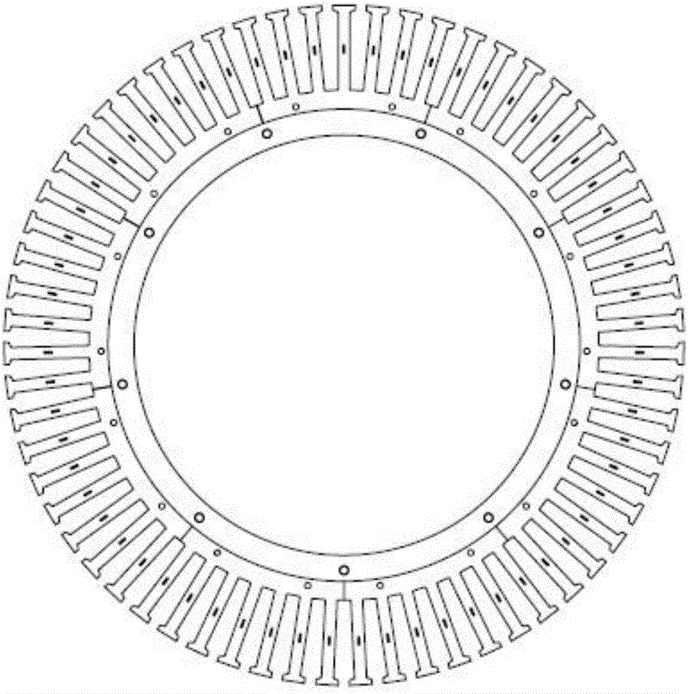
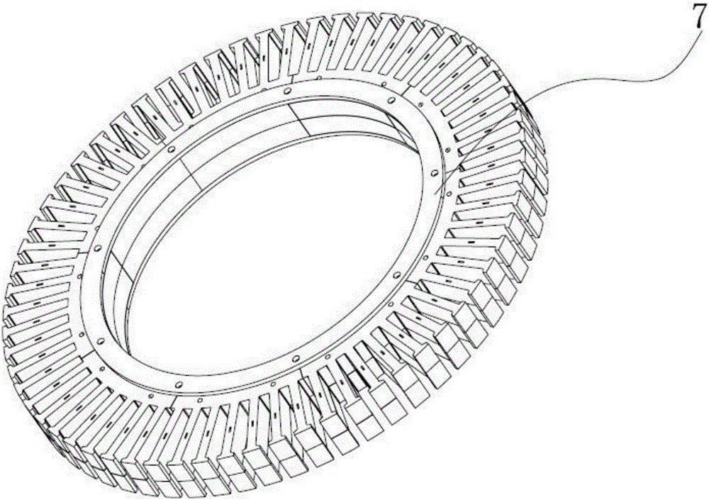
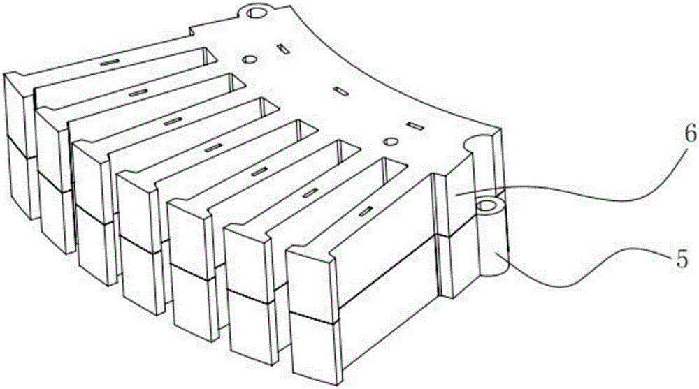
[0028] Such as Figure 1-8 As shown, the embodiment of the present invention relates to an external tooth internal stator structure of a motor and a manufacturing method thereof. The corresponding stator includes a silicon steel sheet stack 6 composed of several silicon steel sheets stacked in sequence, and several silicon steel sheets are stacked. Groups 6 are superimposed in sequence to form a stator splicing group, and seve...


PUM


Abstract

The invention relates to an outer-tooth and inner-stator structure of a motor and a manufacturing method of the outer-tooth and inner-stator structure. The stator structure comprises silicon steel sheet stacks which are formed by sequentially superposing a plurality of silicon steel sheets, wherein the plurality of silicon steel sheet stacks are sequentially superposed to form stator splicing groups; the plurality of stator splicing groups are transversely butted in sequence to form an annular stator; each silicon steel sheet comprises an arc-shaped base part and one or more outer tooth parts; the outer tooth parts are uniformly arranged at the outer side of each arc-shaped base part; and the adjacent upper and lower silicon steel sheet stacks in the stator splicing groups are arranged in a manner that two ends are in opposite directions. The stator manufacturing method is simple, reliable and low in cost. The stator is assembled in a splicing manner, so that the utilization rate of the sheets can be greatly improved; processing can also be carried out by using a low-tonnage punch press; the cost of equipment is reduced; the automation degree is improved; each sub-part can also be wound and then assembled; and the outer-tooth and inner-stator structure is not limited by a notch width and is suitable for the stator with various requirements.

Description

technical field [0001] The invention relates to the field of motor structure, in particular to an external tooth internal stator structure of a motor and a manufacturing method thereof. Background technique [0002] Whether it is a permanent magnet brushless DC motor driven by a square wave or a permanent magnet AC servo motor driven by a sine wave, the structure of the motor body is basically the same or similar. According to the position of the fixed parts, it is divided into inner stator or outer stator, inner stator The winding teeth on the outer stator are arranged on the outer side, and the corresponding rotor is also on the outer side, while the winding teeth on the outer stator are arranged on the inner side, and the corresponding rotor is also arranged on the inner side, whether it is an inner stator or an outer stator, They are all ring-shaped structures. The existing stators are all stamped and formed in one piece. When stamping, larger plates are used for stampin...

Claims


Application Information

Patent Timeline
Patent Type & Authority Applications(China)
IPC IPC(8): H02K1/14H02K15/02
Inventor 董瑜堂韩军蒋泽丁亚红
Owner PHASE IND DESIGN NINGBO
Why Eureka
Try Eureka