Ozone mixing reactor

A hybrid reactor and ozone technology, applied in epoxy resin coatings, chemical instruments and methods, coatings, etc., can solve the problems of slow reaction process, increased temperature in the tube, limited blocking effect of baffles, etc. It is not easy to achieve. Oxidative corrosion, reduction of ozone content, effect of prolonged residence time

Inactive Publication Date: 2016-12-14
CHENGDU 90 DEGREE IND PROD DESIGN CO LTD
View PDF11 Cites 2 Cited by
  • Summary
  • Abstract
  • Description
  • Claims
  • Application Information

AI Technical Summary

Problems solved by technology

However, this air intake method has major defects: first, the total amount of reaction per unit time is small, and the efficiency is low, which is not conducive to the large-scale processing of the factory; The heat cannot be dispersed and transferred in time, resulting in an increase in the temperature in the tube, a slowing of the reaction process, and a decrease in the corrosion resistance of the gas inlet tube due to the increase in temperature, which is prone to gas leakage accidents; the third is that this technical means has a positive effect on reducing equipment corrosion. The effect is limited, and the problem of the short service life of the stainless steel cavity has not been better resolved
[0009] At the same time, in the prior art, in order to fully react ozone and exhaust gas, baffles are usually provided in the reactor to prolong the residence time of the mixed gas in the reactor, but this method is only suitable for a small amount of Exhaust gas treatment, and there is a limit to the flow rate of the mixed gas in the reactor, that is, when a large amount of mixed gas is pumped into the reactor at a higher flow rate, the blocking effect of the baffle is limited, and the residence time of the mixed gas in the reactor Still very short, the mixing reaction between ozone and exhaust gas is not sufficient, and the efficiency of exhaust gas treatment is low

Method used


Image

  • Ozone mixing reactor
  • Ozone mixing reactor
  • Ozone mixing reactor

Examples


Embodiment Construction

[0041] Below in conjunction with accompanying drawing, the present invention is described in detail.

[0042] In order to make the object, technical solution and advantages of the present invention more clear, the present invention will be further described in detail below in conjunction with the accompanying drawings and embodiments. It should be understood that the specific embodiments described here are only used to explain the present invention, not to limit the present invention.

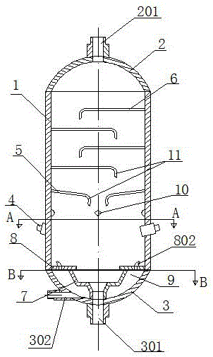
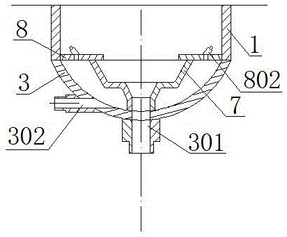
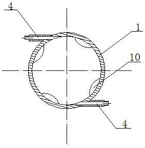
[0043] Such as figure 1 and Figure 8 As shown, an ozone and exhaust gas mixed reactor includes a chamber body 1, the upper end of the chamber body 1 is sealed and connected with an upper head 2 with an air outlet 201, and the lower end of the chamber body 1 is sealed and connected with a liquid outlet connecting pipe 301 and a cooling The lower head 3 of the mouthpiece 302, the side of the cavity 1 are provided with several gas inlet pipes 4, the gas inlet pipes 4 are eccentric tangential ob...


PUM

PropertyMeasurementUnit
thicknessaaaaaaaaaa
thicknessaaaaaaaaaa

Abstract

The invention discloses an ozone mixing reactor which comprises a chamber, wherein a plurality of gas inlet tubes are arranged on the side face of the chamber; the gas inlet tubes are eccentric tangential inclined insertion tubes; at least one downwards inclined sloping baffle is arranged above the gas inlet tubes in the chamber; and a plurality of baffle plates are sequentially arranged above the sloping baffle at intervals according to the axis direction of the chamber. The gas inlet tubes are set as the eccentric tangential inclined insertion tubes, and waste gases and ozone form eddy flow so as to be fully mixed and in full contact with each other, so that the ozone utilization rate is improved, the waste gases and ozone are prevented from directly impacting the wall surface of the chamber, the stress environment of the stainless steel chamber is improved, the stainless steel chamber has low probability of oxidation corrosion, and the problem that the stainless steel chamber is short in life is effectively solved. Due to coordination between the sloping baffle and baffle plates, lots of waste gases are fully treated, the ozone utilization rate is further improved, and the ozone mixing reactor is suitable for treatment of lots of waste gases.

Description

technical field [0001] The invention relates to the field of chemical waste gas treatment equipment, in particular to an ozone and waste gas mixed reactor. Background technique [0002] During the production of chemical products such as phenylethyl alcohol, terpineol, and hydrogenated rosin, the industrial waste gas produced is often foul-smelling gas, which not only pollutes the atmosphere, but also causes direct damage to the human body. The state stipulates that the waste gas discharged from the factory must be Only after the purification reaches the standard can it be discharged to the outside. At present, the treatment of malodorous gas is mainly divided into physical method and chemical method. Physical method includes masking method and dilution diffusion method. Due to its low input cost, simple treatment method and quick effect, it is more suitable A wide range of methods, but because this method aims to alleviate or disperse the stench, it cannot achieve the purpos...

Claims


Application Information

Patent Timeline
Patent Type & Authority Applications(China)
IPC IPC(8): B01D53/76B01D53/48B01D53/52B01D53/54C09D163/10C09D5/16C09D7/12
CPCB01D53/76B01D53/485B01D53/52B01D53/54B01D2251/104C08K3/04C08K3/08C08K3/22C08K3/34C08K9/06C08K13/06C08K2003/085C08K2003/2248C08K2201/014C09D5/1687C09D163/10
Inventor 卢晔
Owner CHENGDU 90 DEGREE IND PROD DESIGN CO LTD
Why Eureka
Try Eureka