Centrifugal separator for processing slime

A technology for centrifugal concentrator and ore slime, which is applied in centrifuge, solid separation, wet separation, etc., can solve the problems of increasing normal pulsation speed and centrifugal acceleration, and can solve the problem of increasing centrifugal acceleration and realizing separation. Choice, simple structure

Active Publication Date: 2016-12-14
深圳市中翰海纳技术有限公司
View PDF7 Cites 3 Cited by
  • Summary
  • Abstract
  • Description
  • Claims
  • Application Information

AI Technical Summary

Problems solved by technology

[0014] In order to solve the problem that the centrifugal acceleration of the rotary flow centrifugal concentrator increases, t

Method used


Image

  • Centrifugal separator for processing slime
  • Centrifugal separator for processing slime
  • Centrifugal separator for processing slime

Examples


Embodiment Construction

[0035]In order to make the technical problems, technical solutions and advantages to be solved by the present invention clearer, the following will describe in detail with reference to the drawings and specific embodiments.

[0036] The invention provides a centrifugal concentrator aiming at the problem that the centrifugal acceleration of the existing centrifugal concentrator increases, and the normal pulsation velocity of the rotary flow increases accordingly.

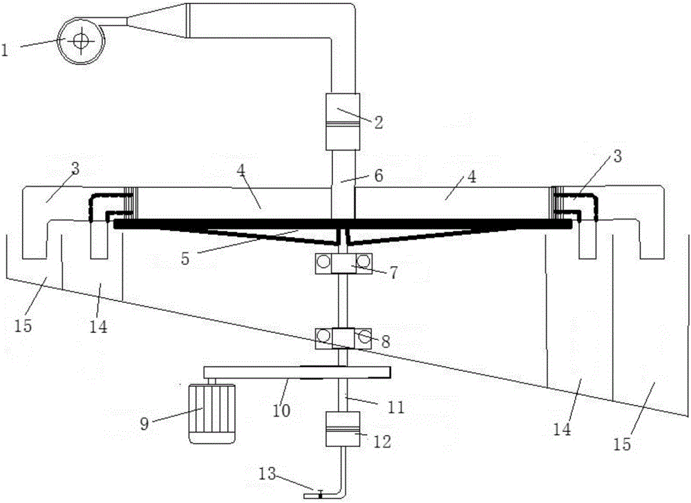
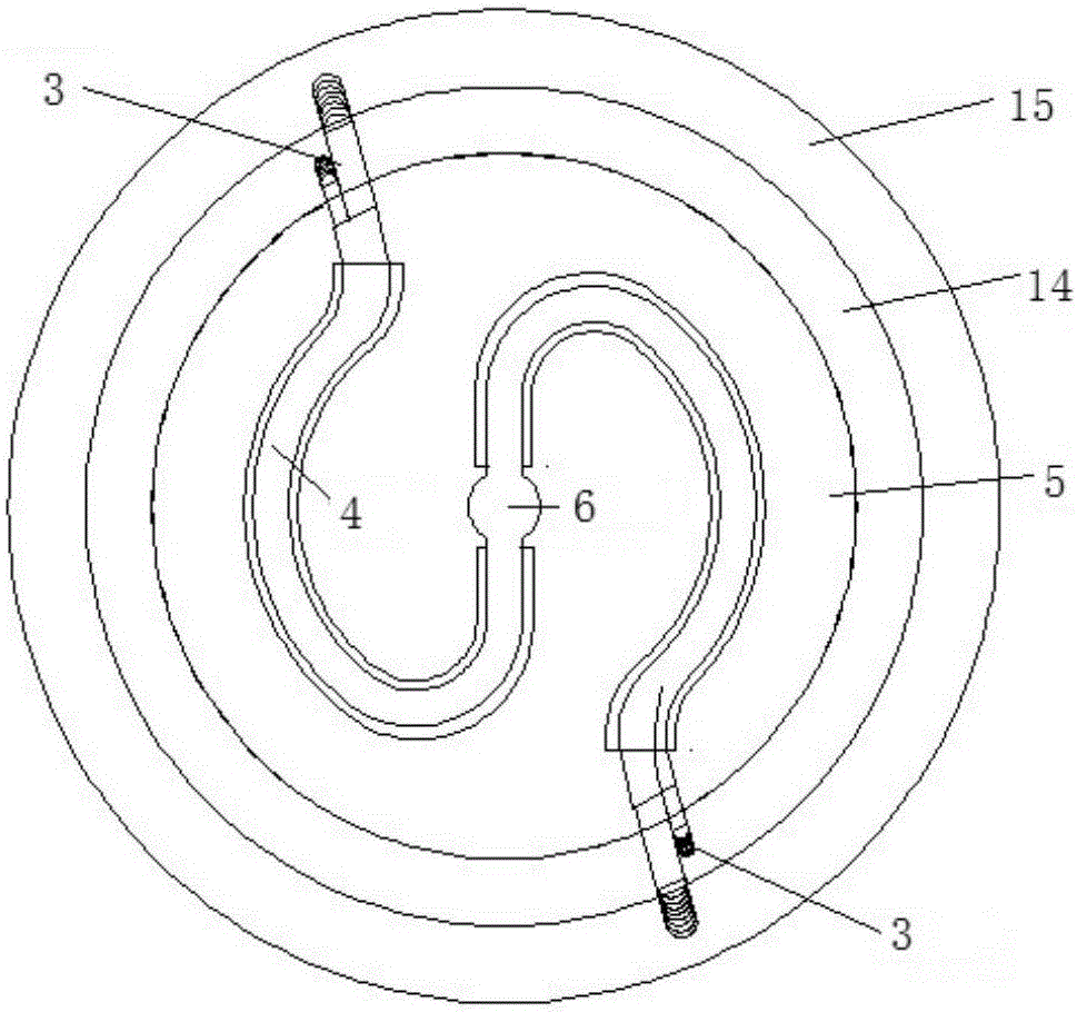
[0037] Such as figure 1 and figure 2 As shown, in the centrifugal concentrator, the sand pump 1 is connected to the slurry rotary connector 2, the slurry rotary connector 2 is connected to the receiver 6, the rotary platform 5 is installed on the hollow transmission shaft 11, and the hollow transmission shaft 11 is installed The upper bearing 7 and the lower bearing 8, the motor 9 drives the hollow transmission shaft 11 through the transmission belt 10; the lower end of the hollow transmission shaft 11 is connected...


PUM


Abstract

The invention provides a centrifugal separator for processing slime and belongs to the technical field of mineral separation equipment. The centrifugal separator comprises a drive rotary system, a water supply system, a material supply system, a sorting system and an unloading system, wherein the drive rotary system is located in the center of the centrifugal separator and used for generating rotational motion to form a centrifugal force field; the water supply system aims to be used for providing backwash water; the material supply system is located on the upper portion of the centrifugal separator and used for supplying materials to the centrifugal separator; and the sorting system is arranged on a rotary platform, the main core component of the sorting system is an enrichment pipe used for sorting processed materials, and the processed materials are divided through a divider to form heavy concentrate and tailings. The centrifugal separator is simple in structure, the problem that as the centrifugal acceleration of an existing centrifugal separator is increased, the normal pulse speed of rotary flow is also increased can be well solved, and sorting of fine-grain slime is effectively achieved.

Description

technical field [0001] The invention relates to the technical field of mineral processing equipment, in particular to a centrifugal mineral processing machine for processing ore slime. Background technique [0002] Gravity beneficiation relies on the difference in gravity, buoyancy, and drag force of flowing water that particles of different densities experience in the slurry, and then have different settling velocities, so as to achieve effective separation of light and heavy mineral particles. [0003] For traditional inclined flow gravity separation equipment such as shakers and chutes, it mainly depends on the gravity field of the earth. Due to the relatively small gravitational acceleration of the earth, the main disadvantage of this type of equipment is the small processing capacity, and the finer the mineral particles, the smaller the processing capacity. [0004] In the 1960s, scientists introduced rotary motion in the gravity beneficiation process to realize the se...

Claims


Application Information

Patent Timeline
IPC IPC(8): B04B5/00B04B9/02B04B9/08B04B11/00B04B7/00B03B5/32
CPCB03B5/32B04B5/00B04B7/00B04B9/02B04B9/08B04B11/00
Inventor 郭民袁长斌梁亚平
Owner 深圳市中翰海纳技术有限公司
Why Eureka
Try Eureka