Aerial wind-energy power-station aircraft and aerial fixation aircraft device

A technology for aircraft and power stations, applied to lighter-than-air aircraft, aircraft, circuit devices, etc., can solve problems such as inability to improve photoelectric conversion rate, low power generation, and inability of solar panels to track sunlight

Inactive Publication Date: 2016-12-14
吕怀民 +1
View PDF25 Cites 13 Cited by
  • Summary
  • Abstract
  • Description
  • Claims
  • Application Information

AI Technical Summary

Problems solved by technology

1. Most of the existing aircraft rely on the airport to take off and land, and cannot take off and land vertically
2. The existing vertical take-off and landing helicopters have a short flight range and a slow speed
3. The existing aircraft is not safe, as long as an accident occurs in the air, it may cause a fall
4. Existing aircrafts are expensive and complicated to control, which limits their widespread use; it is not as easy as cars to widely enter the family and private daily fields
5. Existing aircraft only have the function of being a means of transportation, without adding the function of being an air power station
6. Existing aircraft can only be parked on the ground, not in the air
7. Existing aircraft have not fully developed the excellent structure of electric powered parachute
1. Existing powered parachutes only rely on lift to fly, and do not make full use of buoyancy instead of lift to reduce lift energy consumption and save fuel and energy
2. Existing paramotors consume liquid fuel and do not make full use of solar power
3. Most of the existing powered parachutes take off and land horizontally, and cannot take off and land vertically
4. The existing powered parachute is not safe, as long as an accident occurs in the air, it may cause a fall
1. Since the airborne fixed aircraft device (13) is not used, the external po

Method used


Image

  • Aerial wind-energy power-station aircraft and aerial fixation aircraft device
  • Aerial wind-energy power-station aircraft and aerial fixation aircraft device
  • Aerial wind-energy power-station aircraft and aerial fixation aircraft device

Examples


Embodiment 1

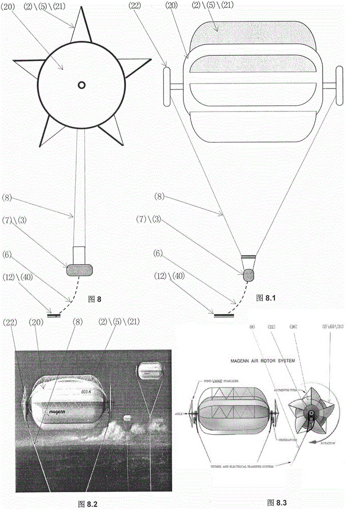
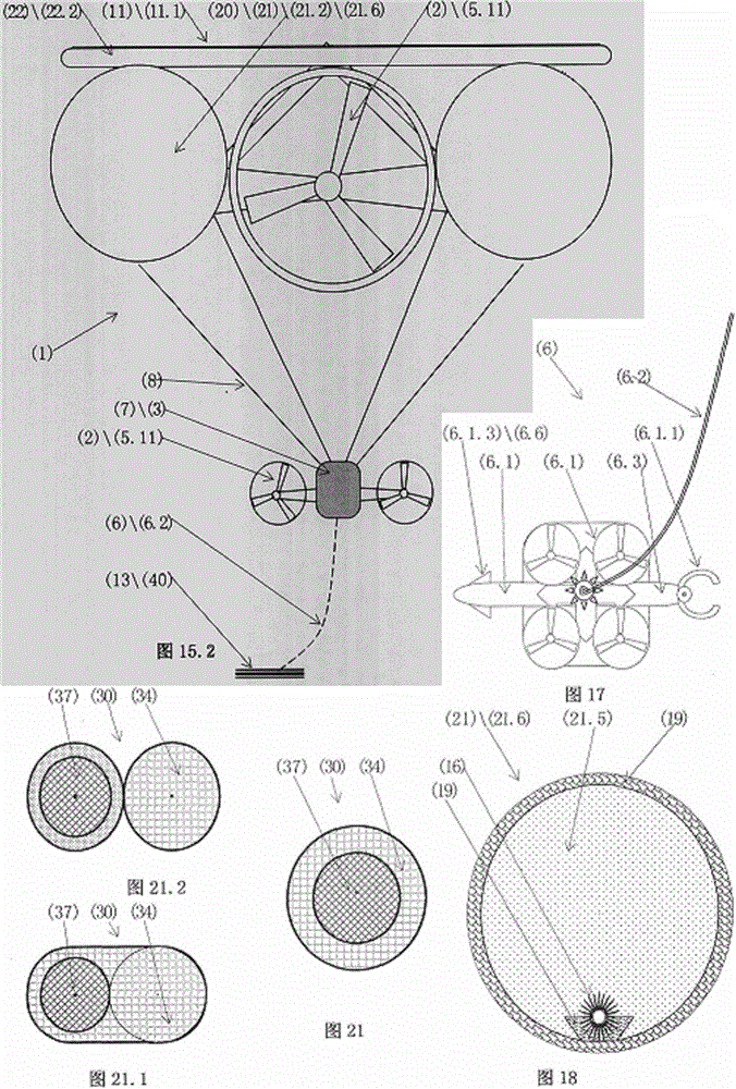
[0149] Example 1. from figure 1 , Figure 1.1 , Figure 1.2 , Figure 1.3 , Figure 1.4 , figure 2 , Figure 2.1 , Figure 2.2 , figure 2 , Figure 2.1 , Figure 2.2 , Figure 17 It can be seen that it is a suspended air wind power station type aircraft that adopts a flexible umbrella wing---the buoyancy force assembly (24).

[0150] It is characterized in that it includes an aircraft (1), an airborne wind power generation system (2), a power storage system (3), a control system (4), a power propulsion system (5), a grounding water receiving system (6), Load loading system (7), sling group system (8) with adjustable length, and transfer system (9);

[0151] The aircraft (1) is connected to the following two systems, the airborne wind power generation system (2) and the load loading system (7); the connection between the load loading system (7) and the aircraft (1) or the airborne wind power generation system (2) Including a length-adjustable sling group system (...

Embodiment 2

[0168] Example 2. from Figure 4 , Figure 4.1 It can be seen that it is a suspended air wind power station type aircraft that adopts a flexible umbrella wing---the buoyancy force assembly (24).

[0169] It is characterized in that: the aerial wind power generation system (2) / electric propeller propulsion system (5.1.1) is arranged in the middle of the length-adjustable sling group system (8); other features are the same as those in Embodiment 1.

Embodiment 3

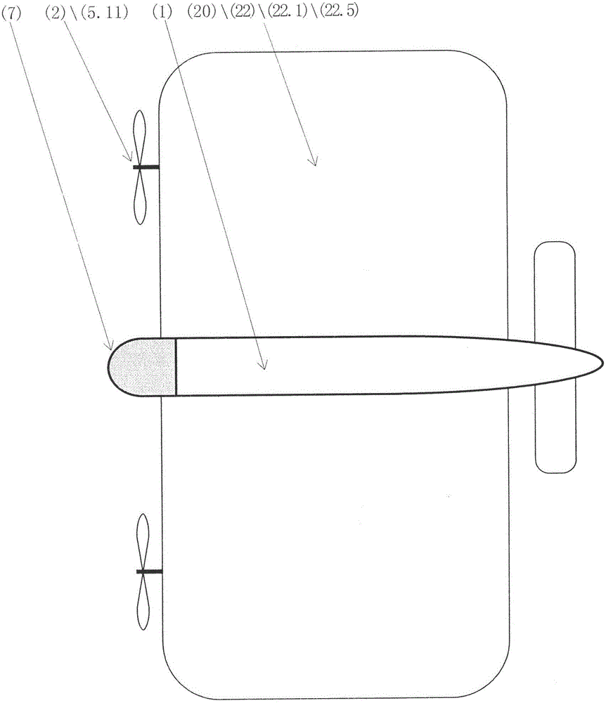
[0170] Example 3. from Figure 5 , Figure 5.1 It can be seen that it is a suspended air wind power station type aircraft that adopts a flexible umbrella wing---the buoyancy force assembly (24).

[0171] It is characterized in that: 2 sets of aerial wind power generation systems (2) / electric propulsion systems (5.1.1) are arranged at the front and rear of the buoyancy body (20) or the buoyancy combination (24); other features are the same as in Embodiment 1.


PUM


Abstract

An aerial wind-energy power-station aircraft relates to the technical field of engineering such as manufacture of power-driven aircrafts, aerial wind power and photoelectricity, aerial transportation and military affairs. The aircraft comprises an aircraft body (1) or a buoyancy lift body (20), a control system (4) and a propelling system (5). The aircraft is characterized in that the aerial wind-energy aircraft also comprises an aerial wind power generation system (2), a storage system (3) of power electric energy and a grounding and water-connecting system (6), wherein the power propelling system (5) comprises an electric propelling flight system (5.1). When the grounding and water-connecting system (6) is connected to an easy-to-connect ground object (12), an aerial fixation aircraft device (13) and a water body (14), the system stays at a stationary state and can start aerial wind-power generation. When the storage system (3) of the power electric energy is filled with aerial wind electricity, the electricity can then be supplied to the electric propelling flight system (5.1), so that flight can be driven. In this way, no fuel is consumed, and the flight can be implemented by ''aerial wind energy and wind electricity''. The aircraft has a very low cost; and by the storage system (3) of the power electric energy or the aerial fixation aircraft device (13), the aerial wind electricity with the very low cost can also be conveyed to the ground for utilization.

Description

technical field [0001] The invention relates to engineering technical fields such as electric aircraft manufacturing, airborne wind power generation, airborne photovoltaic power generation, airborne transportation, airborne mobile houses, military airlift equipment, and military field power generation equipment. Background technique [0002] The existing aircraft has the following problems. 1. Most of the existing aircraft take off and land on the airport, and cannot take off and land vertically. 2. The flight range of existing vertical take-off and landing helicopters is short and slow. 3. The existing aircraft is not safe, as long as an accident occurs in the air, it may cause a fall. 4. Existing aircrafts are expensive and complicated to control, which limits their widespread use in a large number; it is not as easy as automobiles to widely enter the family and private daily fields. 5. The existing aircraft only has a function as a means of transportation, and does not...

Claims


Application Information

Patent Timeline
IPC IPC(8): B64B1/00B64B1/66B64D27/24B64C39/02H02J7/14H02J7/35
CPCB64B1/00B64B1/66B64C39/026B64D27/24H02J7/14H02J7/35Y02T50/60
Inventor 吕怀民吕屾
Owner 吕怀民
Why Eureka
Try Eureka