Wind driven generator

A technology for wind turbines and generators, which is applied in the directions of wind turbines, wind turbine combinations, and wind power generation, etc., can solve the problems of difficulty in removing tip ice, difficulty in heating, and difficulty in deicing blades.

Active Publication Date: 2016-12-14
DONGGUAN UNIV OF TECH
View PDF4 Cites 9 Cited by
  • Summary
  • Abstract
  • Description
  • Claims
  • Application Information

AI Technical Summary

Problems solved by technology

First, the air enters from the tail of the cabin, which is usually inconsistent with the wind direction during operation, making it difficult to enter the wind; secondly, the incoming air must be filtered, sometimes heated or flow controlled, which requires the addition of many other devices, making the cabin more crowded , and once the air inflow speed is relatively large, it is difficult to control the air, and heating will be more difficult
The air enters from the bottom of the tower. Since the tower is tens of meters high, it is difficult for the air to reach the cabin after it flows in. These problems will increase the difficulty

Method used


Image

  • Wind driven generator
  • Wind driven generator
  • Wind driven generator

Examples


Embodiment Construction

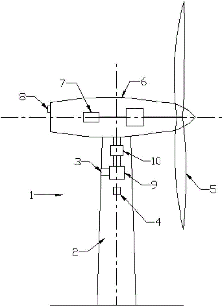
[0027] figure 1 is a perspective view of an exemplary wind turbine, showing various components of the wind turbine. Wherein the wind-driven generator 1 is a horizontal-axis generator, or may also be a vertical-axis generator. In this embodiment, the wind-driven generator 1 includes a tower 2 extending from a supporting surface, and the height of the tower 2 is usually tens of meters. The nacelle 6 installed on the tower 2, the generator 7 arranged in the nacelle, and the gearbox connected to the generator 7, the rotor of the wind power generator 2 is rotatably connected to the gearbox through the shaft, and the rotor includes a hub and an external Blade 5.

[0028] In this embodiment, the rotor comprises three rotor blades 5 . In an alternative embodiment, the rotor comprises more or less than three rotor blades 5 . Rotor blades 5 are spaced around the hub to facilitate rotation of the rotor, thereby converting kinetic energy from the wind into usable mechanical energy and ...


PUM


Abstract

The invention discloses a wind driven generator. The wind driven generator comprises a tower drum fixed to the ground, a cabin located on a tower frame, a power generator arranged in the cabin, a rotor which rotates relative to the cabin and comprises a plurality of rotor blades, and an air circulation system used for deicing the blades and enabling the blades, the cabins and the tower drum to communicate. The air circulation system comprises a controllable air inlet formed in the position, away from the cabin by a certain distance, of the tower drum, an air filter arranged on the upper portion of the air inlet, a heater arranged on the upper portion of the air filter, and an internal heat exchanger used for heat exchange with the power generator in the cabin. Airflow circulation passages are arranged in the blades. Through the airflow circulation passages, airflow entering the blades flow through blade tips firstly and then flow through roots, and the airflow is exhausted out through small holes in the roots. By the adoption of the deicing system, the temperature, cleanliness and flow of air entering the cabin are controlled more effectively, the system does not occupy any space of the cabin, and the overall deicing effective is better.

Description

technical field [0001] The present invention relates generally to wind power generators, and more particularly to deicing of rotor blades of wind power generators. Background technique [0002] In recent years, wind power has attracted more and more attention as an environmentally friendly and relatively cheap alternative energy source. As interest in wind power continues to grow, considerable effort has been devoted to the development and production of reliable and efficient wind turbines. [0003] Typically, wind turbines include a rotor with multiple blades mounted within a housing or nacelle on top of a frame or tubular tower, available wind turbines may have large rotors (eg 30 meters in diameter or more). The blades of these rotors convert wind energy into a rotational torque or force that drives one or more generators, which are connected to the rotor through a gearbox. The gearbox boosts the inherently low rotational speed of the turbine rotor, allowing the generat...

Claims


Application Information

Patent Timeline
IPC IPC(8): F03D80/40F03D9/25
CPCY02E10/72
Inventor 尹玲
Owner DONGGUAN UNIV OF TECH
Why Eureka
Try Eureka