Power equipment safety monitoring system based on wireless network

A security monitoring system and power equipment technology, applied in the direction of power network operating system integration, information technology support system, electrical components, etc., can solve the problems of poor system operation stability, difficult maintenance, complicated wiring, etc., to achieve stable operation and save maintenance time, the effect of reducing power consumption

Active Publication Date: 2016-12-14
STATE GRID SICHUAN ELECTRIC POWER COMPANY NEIJIANG POWER SUPPLY +1
View PDF4 Cites 4 Cited by
  • Summary
  • Abstract
  • Description
  • Claims
  • Application Information

AI Technical Summary

Problems solved by technology

[0002] In the current power grid erection, unattended substations have been widely used. The establishment of the centralized control center enables the management and operation tasks of the substation to be realized remotely by the centralized control center, and the operators do not need to enter the substation site. In this mode, the substation’s All monitoring information needs to be uploaded to the centralized control center, and the remote control and remote adjustment operation commands issued by the centralized control center directly reach the on-site actuators of the substation to control the actions of on-site equipment. However, in the existing power equipment safety monitoring system, serial Data transmission, not only complex wiring, difficult maintenance, but also high power consumption, poor stability of system operation

Method used


Image

  • Power equipment safety monitoring system based on wireless network
  • Power equipment safety monitoring system based on wireless network

Examples


Embodiment 1

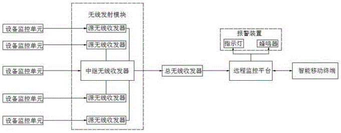
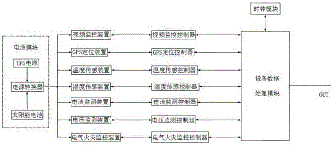
[0027] like figure 1 and figure 2 As shown, a wireless network-based power equipment safety monitoring system includes an equipment monitoring unit, a wireless transceiver module, a total wireless transceiver, a remote monitoring platform, an alarm device, and an intelligent mobile terminal. Each power equipment is equipped with a device Monitoring unit and wireless transceiver module. The equipment monitoring unit includes a power supply module, equipment data acquisition module and equipment data processing module. The power supply module is used to provide working voltage to the equipment data acquisition module, equipment data processing module and wireless transceiver module. The equipment data acquisition module It is used to collect the operation information of electric power equipment. The equipment data acquisition module is electrically connected with the equipment data processing module, and the output end of the equipment data processing module is electrically con...

Embodiment 2

[0031] This embodiment is a further improvement made on the basis of the above embodiments, such as figure 1 and figure 2 As shown, in this embodiment, the equipment data processing module includes a TM4C123G single-chip microcomputer, and the equipment data acquisition module includes a video monitoring device, a GPS positioning device, a temperature sensing device, a humidity sensing device, a current monitoring device, a voltage monitoring device and an electrical fire monitoring device. A monitoring device, a video monitoring controller is connected between the video monitoring device and the equipment data processing module, a GPS positioning controller is connected between the GPS positioning device and the equipment data processing module, and a connection is made between the temperature sensing device and the equipment data processing module A humidity sensing controller is connected between the humidity sensing device and the equipment data processing module, a curre...

Embodiment 3

[0035] This embodiment is a further improvement made on the basis of the above embodiments, such as figure 1 and figure 2 As shown, in this embodiment, the source wireless transceiver includes the AT86RF212 chip, the relay wireless transceiver and the total wireless transceiver both include the Si4432 chip, the source wireless transceiver does not need a strong transmission capability, and low power consumption and low The chip of transmitting power is used to reduce the cost of the present invention, while the relay wireless transceiver and the total wireless transceiver need strong signal transceiving and transmission capabilities to ensure the stability of the present invention. In addition, the relay wireless transceiver also includes an RF front-end transmitting chip to enhance the transmission capability of the relay wireless transceiver and expand the monitoring range of the present invention.


PUM


Abstract

The invention discloses a power equipment safety monitoring system based on a wireless network. The power equipment safety monitoring system comprises an equipment monitoring unit, a wireless receiving-transmitting module, a main wireless transceiver, a remote monitoring platform, an alarm device and an intelligent mobile terminal, wherein the equipment monitoring unit and the wireless receiving-transmitting module are arranged in each piece of power equipment; two kinds of wireless receiving-transmitting modules are arranged in the power equipment; one kind of wireless receiving-transmitting module comprises a wireless transceiver; and the other kind of wireless receiving-transmitting module comprises a relay wireless transceiver. In the power equipment safety monitoring system, 5 to 10 pieces of power equipment are divided into a group, and the wireless receiving-transmitting module in one piece of power equipment in each group communicates with the main wireless transceiver of the system, so that the power consumption of a source wireless transceiver is lowered; the data transmission capability of the power equipment safety monitoring system is enhanced; and the power equipment safety monitoring system runs more stably. Moreover, when the remote monitoring platform monitors that certain power equipment encounters an exception, maintenance personnel can go to the exceptional power equipment to repair in time no matter where the maintenance personnel is, so that the repair time of the power equipment is saved.

Description

technical field [0001] The invention relates to the technical field of power equipment network monitoring, in particular to a wireless network-based power equipment safety monitoring system. Background technique [0002] In the current power grid erection, unattended substations have been widely used. The establishment of the centralized control center enables the management and operation tasks of the substation to be realized remotely by the centralized control center, and the operators do not need to enter the substation site. In this mode, the substation’s All monitoring information needs to be uploaded to the centralized control center, and the remote control and remote adjustment operation commands issued by the centralized control center directly reach the on-site actuators of the substation to control the actions of on-site equipment. However, in the existing power equipment safety monitoring system, serial Data transmission is not only complicated in wiring and diffi...

Claims


Application Information

Patent Timeline
Patent Type & Authority Applications(China)
IPC IPC(8): H02J13/00
CPCH02J13/0075H02J13/0079Y04S20/242Y04S40/126Y02B70/30Y02E60/00
Inventor 程崯
Owner STATE GRID SICHUAN ELECTRIC POWER COMPANY NEIJIANG POWER SUPPLY
Why Eureka
Try Eureka