Water cooling method for motor

A technology of water cooling and water pipes, applied in the direction of electrical components, electromechanical devices, electric components, etc., can solve the problems of increasing production difficulty and manufacturing cost, unsatisfactory heat dissipation and cooling effect, complex structure, etc., to improve heat dissipation effect, prevent cracks, The effect of preventing safety accidents

Inactive Publication Date: 2016-12-14
吴继成
View PDF5 Cites 4 Cited by
  • Summary
  • Abstract
  • Description
  • Claims
  • Application Information

AI Technical Summary

Problems solved by technology

[0005] In the process of use, we found that although the cooling effect of the existing water-cooled motor is improved compared with the way of using the cooling fan alone, the cooling effect is still not ideal; more importantly, the existing auxiliary cooling method not only needs Adding at least 4 more self-made parts, the structure is very complicated, and often needs to change the internal structure of the motor, which greatly increases the production difficulty and manufacturing cost, and in order to take away the heat of the motor through the cooling water, these added parts A water-cooling cavity for cooling water flow is formed between the shell and the shell, which puts forward high precision requirements for the manufacturing accuracy of the shell and the waterproof sealing of the water-cooling cavity. The internal energized parts come into contact, resulting in electric shock, which can lead to serious safety accidents

Method used


Image

  • Water cooling method for motor
  • Water cooling method for motor

Examples


Embodiment Construction

[0022] Below in conjunction with accompanying drawing and embodiment the present invention will be further described:

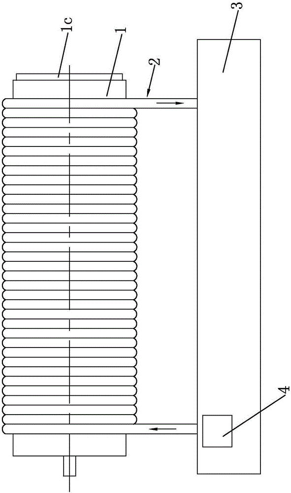
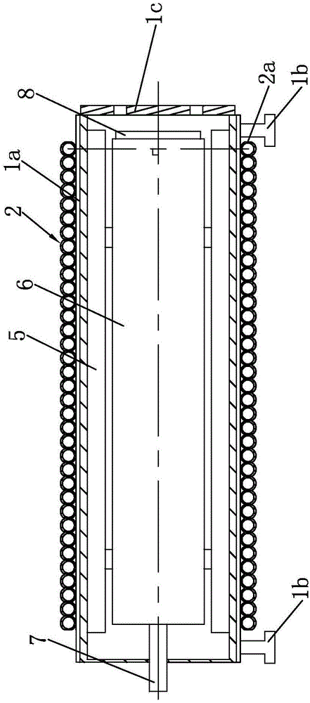
[0023] Such as figure 1 , 2 As shown, a water cooling method for a motor includes a casing 1 and a heat dissipation fan 8, wherein the casing 1 is an aluminum casting, and a group of axial cooling grooves 1a are evenly distributed on the outer wall of the casing 1 along the circumferential direction, and the two ends of the bottom of the casing 1 are respectively There is a mounting bracket 1b. The stator 5 is installed in the stator installation groove on the inner wall of the housing 1, and the stator rotatably cooperates with the rotor 6, and its specific installation structure is in the prior art. The output shaft 7 at one end of the rotor 6 passes through the through hole on the casing 1, and there is a cooling fan 8 at the other end of the rotor. hole. When the motor is working, the heat in the motor casing is mainly discharged from the cooling fan ...


PUM


Abstract

The invention discloses a water cooling method for a motor. The water cooling method includes a step a of arranging a rubber water pipe outside a housing in such a manner that the rubber water pipe winds on a housing between two mounting bases along the axial direction to form a spiral structure, wherein one end of the rubber water pipe is a water inlet end and the other end of the rubber water pipe is a water outlet end; a step b of communicating the water inlet end and the water outlet end of the rubber water pipe with a same water tank where a water pump and a cooler for cooling the cooling water are arranged; and a step c of injecting clear water for cooling in the water tank before working of the motor, and starting the water pump and the cooler during working of the motor to allow the cooling water to circulate between the water tank and the rubber water pipe. A water pipe is wound outside the housing, and material of the water pipe, the winding means of the water pipe and the internal diameter ratio of the water pipe and housing are perfectly chosen to form an inseparable part of the method, so as to improve the heat radiation effect along the radial direction.

Description

technical field [0001] The invention belongs to the field of electric motors, in particular to a water cooling method for electric motors. Background technique [0002] The motor is a widely used power device. It is generally composed of a casing, a stator and a rotor. The outer wall of the casing is provided with a set of axial cooling grooves along the circumference, and the two ends of the bottom of the casing are respectively provided with a mounting support. . The inner wall of the shell is fixed with a stator, which rotates with the rotor, and the output shaft on the rotor passes through the through hole at one end of the shell, and the other end of the shell is equipped with a heat dissipation end cover, which is used to protect the motor cooling fan inside. When in use, the motor will generate heat. If the heat is not effectively dissipated, it will not only affect the transmission efficiency and precision, but also affect the service life of the motor. Although t...

Claims


Application Information

Patent Timeline
Patent Type & Authority Applications(China)
IPC IPC(8): H02K5/20H02K9/19
CPCH02K5/20H02K9/19
Inventor 吴继成吴丹
Owner 吴继成
Why Eureka
Try Eureka