A dehumidification type filter placement device

A filter and dehumidification technology, applied in the field of dehumidification filter placement devices, can solve the problems of incomplete dehumidification, single function, complicated operation, etc., and achieve the effects of complete dehumidification, multiple economic benefits, and easy operation.

Inactive Publication Date: 2018-12-04
江苏沛源泵业制造有限公司
View PDF5 Cites 0 Cited by
  • Summary
  • Abstract
  • Description
  • Claims
  • Application Information

AI Technical Summary

Problems solved by technology

[0007] In order to overcome the disadvantages of incomplete dehumidification, single function and complicated operation of the existing placement device, the technical problem to be solved by the present invention is to provide a dehumidification type filter placement device with complete dehumidification, multiple functions and easy operation

Method used


Image

  • A dehumidification type filter placement device
  • A dehumidification type filter placement device
  • A dehumidification type filter placement device

Examples


Embodiment 1

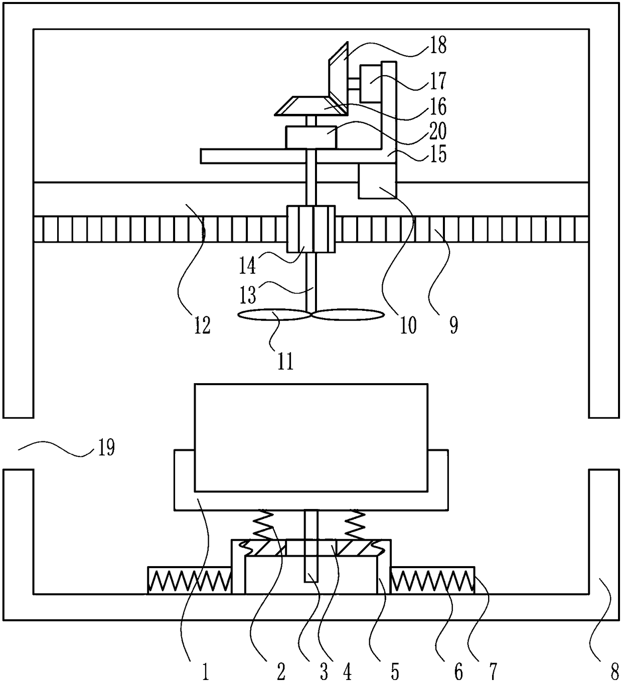
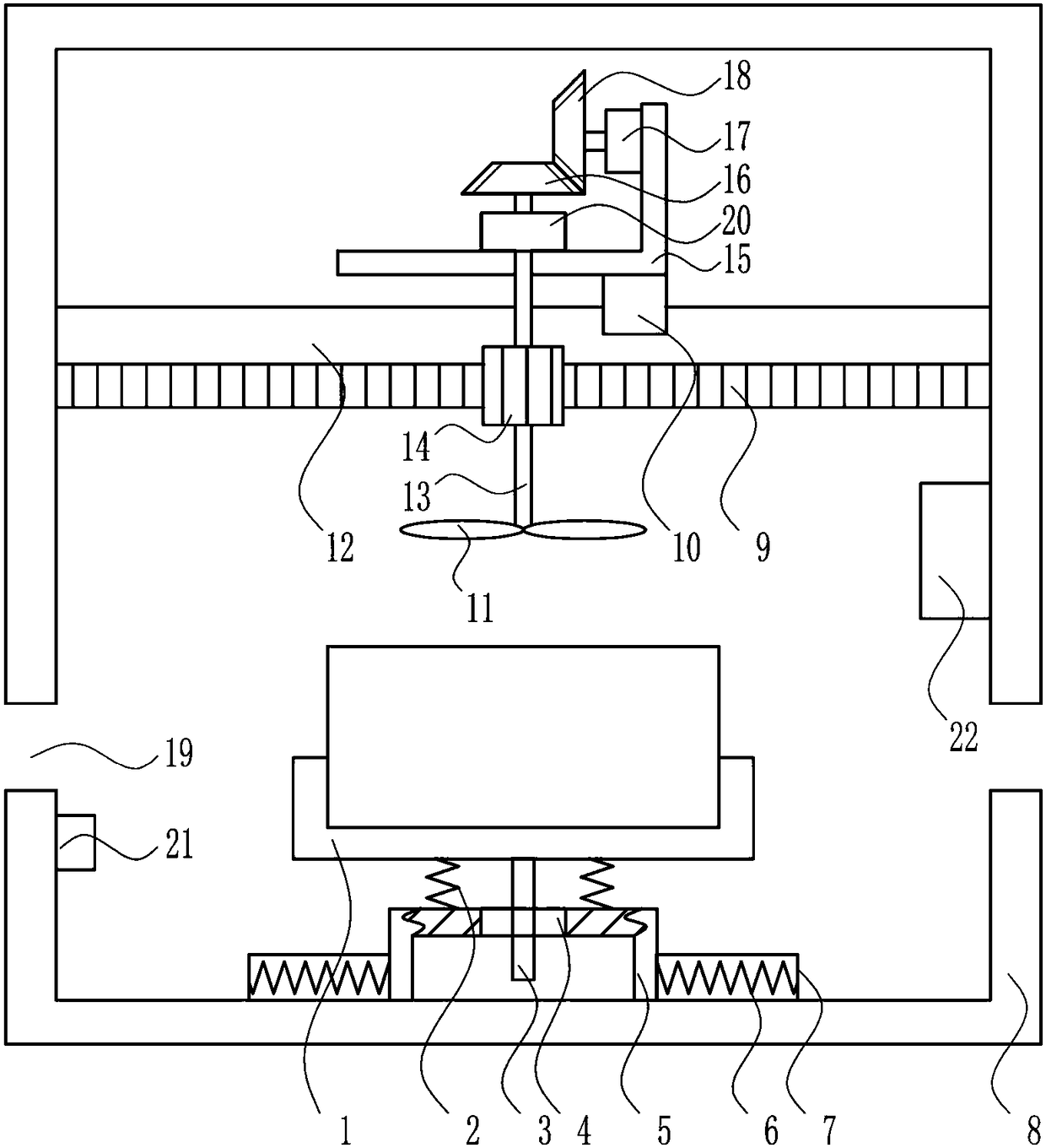
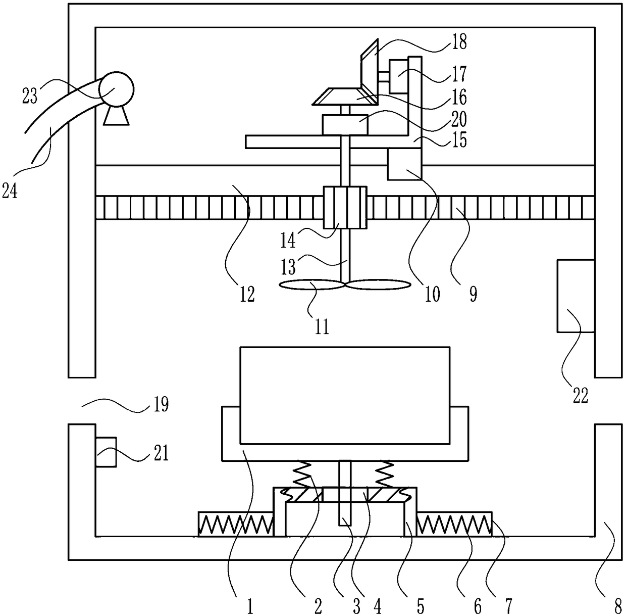
[0037] A dehumidification type filter placement device such as Figure 1-5 As shown, it includes a placement tank 1, a first spring 2, a pole 3, a guide rod 5, a heating wire 6, a housing 7, a box body 8, a rack 9, a slider 10, a blade 11, a slide rail 12, Rotating shaft 13, first gear 14, L-shaped plate 15, first bevel gear 16, motor 17, second bevel gear 18 and bearing seat 20, the left and right sides of the box body 8 are symmetrically opened with openings 19, and the left and right sides of the box body 8 inner bottom Both sides are symmetrically provided with a housing 7, and the housing 7 is provided with a heating wire 6. In the middle of the bottom of the box body 8, a guide rod 5 is provided. The guide rod 5 is provided with a guide hole 4. There is a first spring 2, the top of the first spring 2 is provided with a placement tank 1, the bottom of the placement tank 1 is provided with a support rod 3, the support rod 3 passes through the guide hole 4, and there is a s...


PUM


Abstract

The invention relates to an accommodating device, in particular to a dehumidification type filter accommodating device. The dehumidification type filter accommodating device aims to achieve complete dehumidification and realize multiple functions and convenient operation. To realize the technical purposes, the dehumidification type filter accommodating device comprises an accommodating tank, first springs, a support rod, a guide rod, electric heating wires, shells, a box, a rack, a sliding block, blades, a sliding rail, a rotary shaft, a first gear and the like, wherein openings are symmetrically formed in the left side and right side of the box, the shells are symmetrically arranged on the left side and right side of the bottom in the box, the electric heating wires are arranged in the shells, the guide rod is arranged in the middle of the bottom in the box, a guide hole is formed in the guide rod, and the first springs are symmetrically arranged on the left side and right side of the top of the guide rod. The effects of achieving complete dehumidification and realizing multiple functions and convenient operation are realized. Functions such as cooling and dedusting can be realized at the same time, so that functional diversity can be achieved.

Description

technical field [0001] The invention relates to a placement device, in particular to a dehumidification filter placement device. Background technique [0002] Dehumidification is to compress the air and then cool it, so that the moisture in the air condenses into water. Air with low humidity is obtained by removing the condensed water and reheating it. The surface of the adsorbent has a porous structure, and the moisture in the air is adsorbed on the surface due to capillary action, so it has a hygroscopic effect. [0003] Filters, power transmission and distribution systems operate under fixed-frequency sinusoidal voltage and current waveforms, but when nonlinear loads—such as thyristor rectifiers, frequency converters and electric arc furnaces—are connected to the system, a large number of harmonic currents will be generated, As a result, voltage and current distortions are caused, and harmonic filters are the best way to suppress grid voltage and current distortions. ...

Claims


Application Information

Patent Timeline
Patent Type & Authority Patents(China)
IPC IPC(8): B01D53/26
CPCB01D53/005B01D53/26B01D2257/80B01D2258/06
Inventor 谢航洋
Owner 江苏沛源泵业制造有限公司
Why Eureka
Try Eureka