Cap arranging device

A technology for unscrambling caps and bottle caps, which is applied in the field of cap unscrambling devices for output after sorting bottle caps, which can solve the problems of large compressed air consumption, increased accumulation of equipment damage, and loud noise, so as to reduce gas consumption and noise impact, The effect of improving work efficiency and simplifying equipment structure

Active Publication Date: 2016-12-21
GUANGZHOU TECH LONG PACKAGING MACHINERY CO LTD
View PDF8 Cites 10 Cited by
  • Summary
  • Abstract
  • Description
  • Claims
  • Application Information

AI Technical Summary

Problems solved by technology

[0004] It can be seen that in this kind of cap sorting device, both the front cap and the reverse cap will be sent to the cap selector for screening, and the reverse cap must be blown out from the conveying channel with a relatively large force and enter the bottle cap recovery mechanism, which requires The cap selector has a relatively complex structure and a large volume; at the same time, it needs to consume a large amount of compressed air to meet the production requirements, which results in a relatively large production noise; moreover, the reverse cap needs to be recycled and preliminarily arranged After that, it can re-enter the cylinder for screening, which seriously affects the production efficiency; in addition, whether the reverse cover is sent to the recovery mechanism or re-sent into the cylinder, it will collide with the cylinder and the conveying channel, which will increase the damage to the equipment. accumulation, reducing its service life; in addition, this kind of cover device can only handle such as Figure 4 The "flat cap" shown - this kind of bottle cap is cylindrical, its top and bottom are flat, and it is impossible to deal with the uneven top or bottom, especially the "convex" shaped bottle cap, such as Figure 5 Shown is a schematic structural view of the convex cover, including a cover body 201, and the cover body is provided with an outwardly protruding boss 202

Method used


Image

  • Cap arranging device
  • Cap arranging device
  • Cap arranging device

Examples


Embodiment Construction

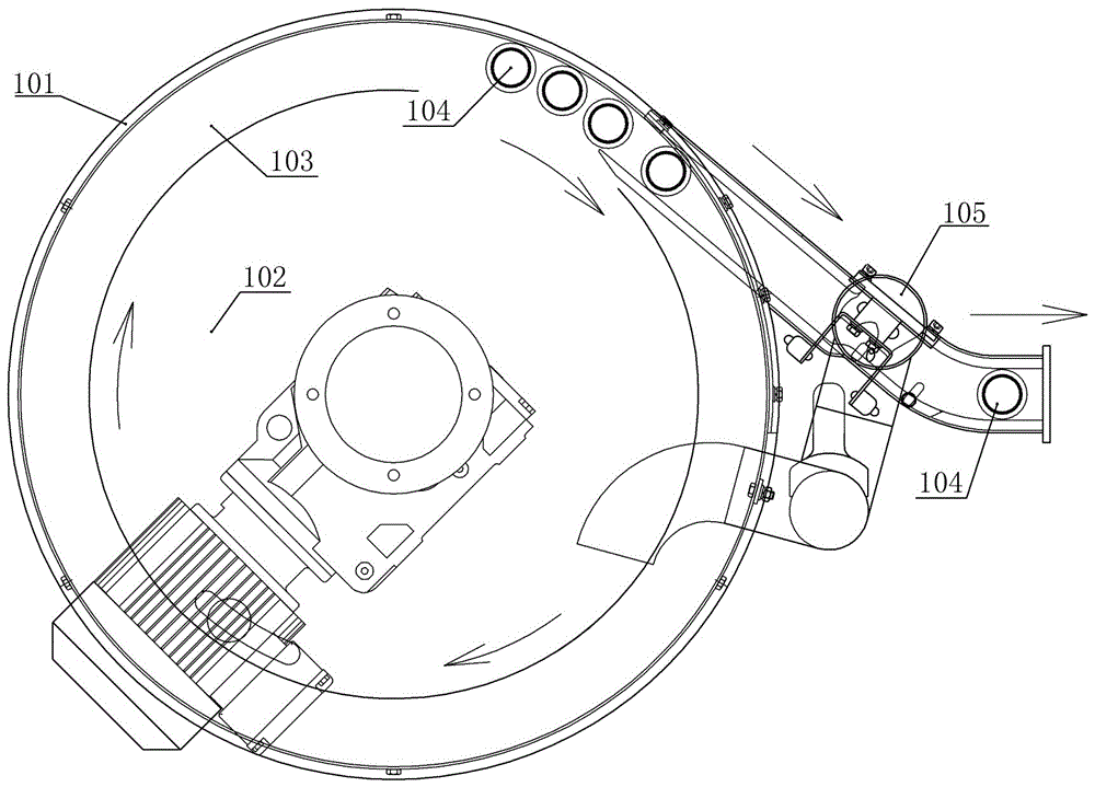
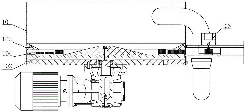
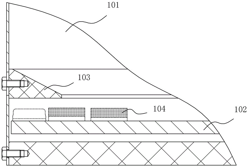
[0017] Such as Figure 6-8 As shown, a cap sorting device includes a cylinder 1, a rotating turntable 2, an annular retaining ring 3 and an output channel 4 for outputting bottle caps. The turntable is installed in the cylinder, and the annular retaining ring is installed above the turntable. There is an outlet connected to the output channel along the tangential direction on the cylinder. A guide block 5 for screening and guiding the bottle cap is installed at the outlet. The guide block is installed above the turntable. The groove 51 that matches the boss 202 of the boss, specifically the groove matches the boss of the bottle cap with the boss upward, and the height of the bottom of the guide block is between the body of the bottle cap 201 and the top surface of the boss, and the guide block The side facing away from the outlet of the cylinder is a guide slope 52 directed from the inner wall of the cylinder to the middle of the cylinder and inclined towards the advancing dir...


PUM


Abstract

The invention discloses a cap arranging device. The diameter of a turntable is smaller than that of a cylinder, a fixed ring is installed between the turntable and the inner wall of the cylinder, an annular retaining ring is installed above the fixed ring, and the width of the annular retaining ring is greater than the diameters of the fixed ring and a bottle cap; even if a part of the annular retaining ring is located above the turntable, both the forward bottle cap and the reverse bottle cap entering the space below the annular retaining ring are not distributed by other bottle caps inside the cylinder; a guide block is installed at the position where the cylinder is connected with the outlet of an output passage; the guide block is provided with a groove corresponding to a boss of the convex bottle cap, so that the forward cap smoothly enters the output passage via the guide block, whereas the reverse bottle cap is guided to the arrangement section of the turntable for rearrangement. The cap arranging device can meet the arrangement requirement of convex bottle caps, and is beneficial to simplifying the structure of equipment, reducing gas consumption and noise influence, guaranteeing the working stability of the equipment, prolonging the service life of the equipment and improving the working efficiency.

Description

technical field [0001] The invention relates to equipment for arranging bottle caps, in particular to a device for arranging and outputting messy bottle caps. Background technique [0002] The cap unscrambling device is a common equipment in the field of beverage filling and pharmaceutical production. During production, the bottle cap is placed on the turntable inside the cylinder. The inner wall of the cylinder moves, and the bottle caps that meet the screening requirements are sent to the next process. [0003] Such as Figure 1-3 As shown, it is a structural diagram of the existing cap sorting device, including a cylinder 101, a rotating turntable 102 is installed in the cylinder, an annular retaining ring 103 is installed above the turntable in the cylinder, and a bottle cap 104 passes through the turntable and the annular retaining ring The gap between them enters the cap selector 105 along the conveying channel. The cap selector screens the caps by limiting the placem...

Claims


Application Information

Patent Timeline
Patent Type & Authority Applications(China)
IPC IPC(8): B65G47/256
CPCB65G47/256
Inventor 杨恢光李智淼宋俊杰
Owner GUANGZHOU TECH LONG PACKAGING MACHINERY CO LTD
Why Eureka
Try Eureka