Control system for optimized combustion of combustor

A technology for optimizing control and control system, applied in the combustion method, control combustion, combustion equipment and other directions, can solve the problems of fuel and air pulsation, affecting combustion efficiency, difficulty in adjusting the loop, etc., to reduce exhaust heat loss, The effect of improving fuel burnout rate and reducing reducing atmosphere

Active Publication Date: 2016-12-21
河北思路科技有限公司
View PDF9 Cites 12 Cited by
  • Summary
  • Abstract
  • Description
  • Claims
  • Application Information

AI Technical Summary

Problems solved by technology

However, under the current operation, detection and control methods of the unit, there are the following problems that directly affect the reasonable monitoring of combustion efficiency: First, under the premise that the unit is put into AGC (Automatic Generation Control), the output of the unit is in a dynamic process of adjustment at any time In the process, the amount of fuel and air always has a large pulsation; secondly, the state of the boiler equipment, such as air leakage and other factors, cannot reflect the real ratio working conditions in the furnace, often making this ratio control unable to be effectively monitored and far from reasonable. Thirdly, the feedback parameters related to the monitoring of the combustion organization and the regulation loop, such as oxygen content, flue gas temperature, NOx emission, etc., are all measured data of the flue gas composition at the tail of the boiler, which is far away from the main combustion area of ​​the boiler. It is very difficult to put the regulating circuit into online automatic operation, and the combustion adjustment mainly depends on the experience of the operating personnel "intermittently", and the adjustment is relatively random

Method used


Image

  • Control system for optimized combustion of combustor
  • Control system for optimized combustion of combustor
  • Control system for optimized combustion of combustor

Examples


Embodiment Construction

[0046] In order to make the purpose, technical solutions and advantages of this application clearer, the technical solutions in this application will be clearly and completely described below in conjunction with the accompanying drawings in this application. Obviously, the described embodiments are part of the embodiments of this application , but not all examples. Based on the embodiments in this application, all other embodiments obtained by persons of ordinary skill in the art without making creative efforts belong to the scope of protection of this application.

[0047] Under the current operation, detection and control mode of the unit, there are the following problems that directly affect the reasonable monitoring of combustion efficiency: First, under the premise that the unit is put into AGC (Automatic Generation Control), since the output of the unit is in the dynamic process of adjustment at any time , the amount of fuel and air always has a large pulsation; secondly...


PUM


Abstract

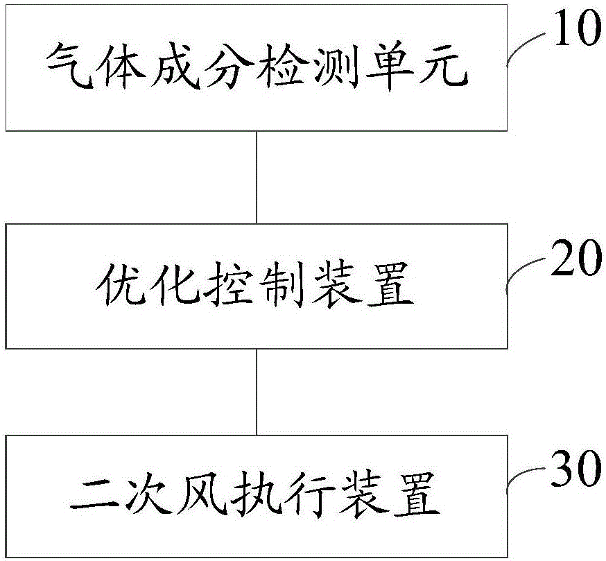
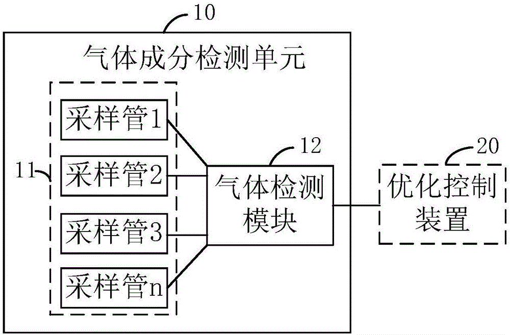
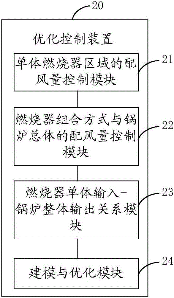
The application discloses a control system for optimized combustion of a combustor. The system comprises a gas component detection unit, an optimized control device and a secondary air executing device, wherein the gas component detection unit is used for detecting smoke component numerical values of a region where the combustor is and of a region of a rear flue of a boiler and sending the detection result to the optimized control device; the optimized control device is connected to the gas component detection unit for receiving the smoke component numerical values detected by the gas component detection unit and generating a control command according to the smoke component numerical values; the secondary air executing device is connected to the optimized control device for receiving the control command sent by the optimized control device and controlling a second air baffle plate executing mechanism according to the control command. According to the technical scheme disclosed by the invention, operation under a relatively low excessive air coefficient is guaranteed by controlling the air supply amount of the combustor, so that the burnout efficiency of fuels is effectively improved, the reducing atmosphere of the boiler is reduced and coking and corroding phenomena are improved while the heat loss due to exhaust gas is reduced, and the combustion process is safe, efficient and low in pollution.

Description

technical field [0001] The present application belongs to the technical field of burner control, and in particular relates to a control system for optimizing combustion of a burner. Background technique [0002] From the analysis of the basic principle of boiler combustion, the uneven distribution or poor mixing of air powder in the furnace will cause local reducing atmosphere, accelerate the corrosion and coking of water wall tubes, or cause overheating of water wall, superheater, and reheater tube walls. , in order to reduce the emission of NOx in the flue gas and reduce the heat loss of the boiler exhaust, the boiler is required to operate at a lower excess air. If the air / powder ratio can be carefully controlled, the boiler can be operated with a relatively low excess air, so that The heat loss of the exhaust smoke is reduced, and due to the decrease of the exhaust gas temperature, the total heat loss will be reduced even more, and the energy consumption of the supply an...

Claims


Application Information

Patent Timeline
Patent Type & Authority Applications(China)
IPC IPC(8): F23N5/00F23N5/26F23L9/00
CPCF23L9/00F23N5/003F23N5/26
Inventor 邢红涛
Owner 河北思路科技有限公司
Why Eureka
Try Eureka