Rotation optical scanning distance measuring device and method

A technology of optical scanning and ranging device, which is applied in the field of ranging, and can solve the problems of easy wear and tear of devices and affecting service life.

Inactive Publication Date: 2016-12-21
北京创想智控科技有限公司
View PDF8 Cites 23 Cited by
  • Summary
  • Abstract
  • Description
  • Claims
  • Application Information

AI Technical Summary

Problems solved by technology

[0007] The purpose of the present invention is to provide a rotating optical scanning distance measuring device and method to solve th

Method used


Image

  • Rotation optical scanning distance measuring device and method
  • Rotation optical scanning distance measuring device and method

Examples


Embodiment 1

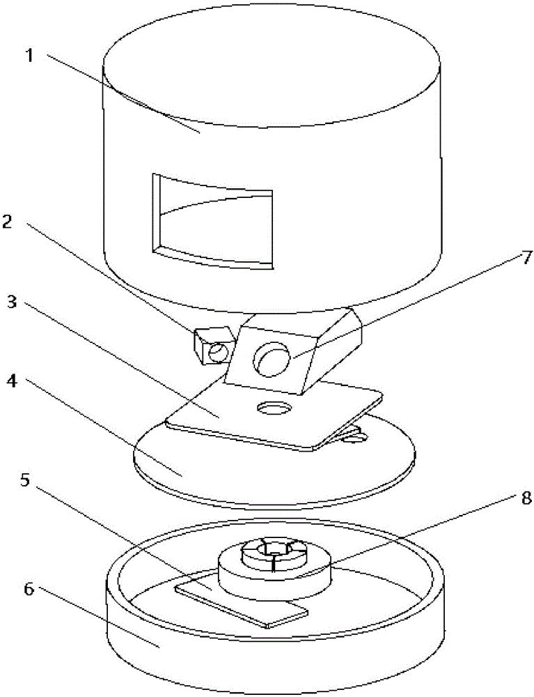
[0046] Such as Figure 1-2 As shown, a rotating optical scanning distance measuring device is provided in this embodiment, and the rotating optical scanning distance measuring device includes a fixed base 6, an angle encoder, a rotating system, a laser distance measuring system, a power supply transmission and a data receiving device 5. Power supply receiving and wireless data transmission device 9 and data processing module;

[0047] The rotating system includes a rotating platform 3, a motor stator 8 and a motor rotor; the electronic stator is fixedly connected to the fixed base 6; the rotating platform 3 is fixedly connected to the motor rotor;

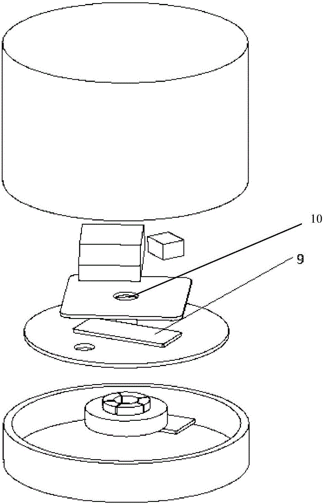
[0048] The center of the housing of the motor rotor is fixedly connected to one end of the support shaft 10; the other end of the support shaft 10 is rotationally connected to the housing of the electronic rotor; the center of the rotating platform 3 is fixed to the support shaft 10 catch;

[0049] The laser ranging system includ...

Embodiment 2

[0073] The rotational optical scanning distance measuring method provided in this embodiment is implemented on the rotational optical scanning distance measuring device provided in the first embodiment.

[0074] Specifically, the rotating optical scanning ranging method includes:

[0075] Step 1. Turn on the power supply, and the stator in the stator of the motor is excited by the embedded wire, thereby driving the rotor to rotate, and the rotating platform of the rotor of the motor rotates, and the angle encoder monitors the rotation speed of the rotating platform, and waits for After the rotating speed of the rotating platform is stable, enter the next step;

[0076] Step 2, the laser light source irradiates the laser beam onto the target object;

[0077] Step 3, the target object reflects the laser beam generated by the laser light source;

[0078] Step 4. The photosensitive device receives the emitted light and converts the image signal into an electrical signal; wherein...


PUM


Abstract

The invention provides a rotation optical scanning distance measuring device and a method and relates to the field of distance measuring. The rotation optical scanning distance measuring device comprises a fixed base, an angle encoder, a rotation platform, a motor rotor, a motor stator, a laser light source, a light sensing device, a power supply transmission and data receiving device and a data processing device. The motor stator drives the rotation plate to rotate through the motor rotor. The laser light source and the light sensing device are fixed on the rotation platform. The light sensing device is used for reflected laser emitted by the laser light source. The power supply transmission and data receiving device is fixedly connected to the fixed base. A power supply receiving and wireless data transmission device is arranged on the rotation platform and is used for receiving data and electric power emitted by the power supply transmission and data receiving device. The power supply receiving and wireless data transmission device is connected with the light sensing device. The angle encoder is fixed on the rotation platform. The data processing module is connected with the angle encoder and the light sensing device. According to the invention, a technical problem that inner devices in a small laser are easily worn is solved.

Description

technical field [0001] The invention relates to the technical field of distance measurement, in particular to a rotating optical scanning distance measurement device and method. Background technique [0002] The optical scanning ranging device is a device for non-contact scanning ranging of the target object through structured light. Scanning the structured light beam to the environment through the rotating mechanism can realize the extraction of environmental contour information. [0003] Compared with methods such as ultrasonic waves and depth cameras, laser has the characteristics of high coherence and high directionality, which can greatly improve the measurement accuracy, so it is widely used in distance measuring devices. The laser ranging method has the characteristics of fast measurement speed and long range. At present, many indoor robot systems use laser ranging devices as sensors to realize positioning, construct maps and barriers. [0004] Laser ranging methods...

Claims


Application Information

Patent Timeline
IPC IPC(8): G01S17/08
CPCG01S17/08
Inventor 凌清吴兴华宋仕超陈猛
Owner 北京创想智控科技有限公司
Why Eureka
Try Eureka