Eureka AIR delivers breakthrough ideas for toughest innovation challenges, trusted by R&D personnel around the world.

Microstructured multicore optical fibre (mmof), a device and the fabrication method of a device for independent addressing of the cores of microstructured multicore optical fibre

A microstructured, multi-core technology, applied in the field of device manufacturing, which can solve problems such as crosstalk and bending loss reduction

Inactive Publication Date: 2016-12-21
信息技术有限公司
View PDF5 Cites 8 Cited by
  • Summary
  • Abstract
  • Description
  • Claims
  • Application Information

AI Technical Summary

Problems solved by technology

[0013] Among the most pressing problems of systems using SMD are the reduction of crosstalk with adjacent transmission channels and the problem of obtaining as little bending loss as possible which will facilitate the installation of fiber optic cables

Method used


Image

  • Microstructured multicore optical fibre (mmof), a device and the fabrication method of a device for independent addressing of the cores of microstructured multicore optical fibre
  • Microstructured multicore optical fibre (mmof), a device and the fabrication method of a device for independent addressing of the cores of microstructured multicore optical fibre
  • Microstructured multicore optical fibre (mmof), a device and the fabrication method of a device for independent addressing of the cores of microstructured multicore optical fibre

Examples


example I

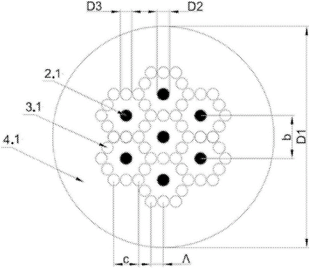
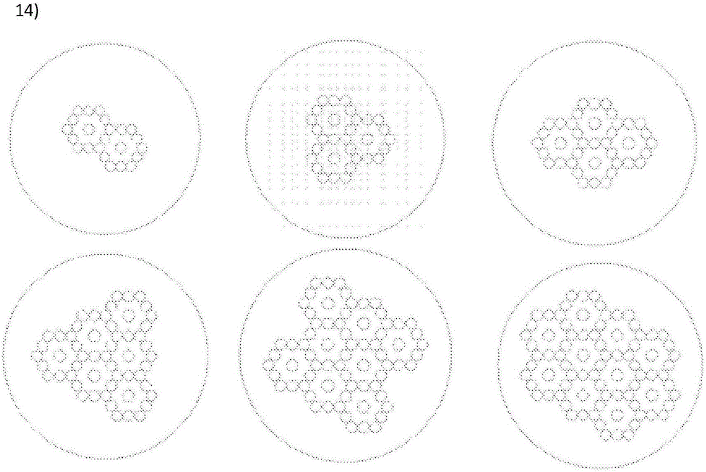
[0062] Microstructured multi-core optical fiber according to the invention and intended for transmission, further, the microstructured multi-core guide fiber according to the invention comprises regions with microstructures in which base units are embedded, each of them comprising A core of doped silica glass, around which are longitudinal pores filled with air, (further, said pores) located in a matrix of silica glass.

[0063] For a light wavelength of λ = 1550 nm, the difference between the refractive indices of the core material and cladding (outer and inner) corresponds to Δ = 5.2 10 -3 ±0.5·10 -3 .

[0064] The base unit is characterized by a D2 core diameter, a D3 pore diameter and a lattice constant Λ corresponding to the distance between the centers of adjacent pores. The center of the hole is positioned on the vertices and midpoints of the sides of the hexagon, the center of which is represented by the core; the length of the side c of the hexagon formed by the axi...

example II

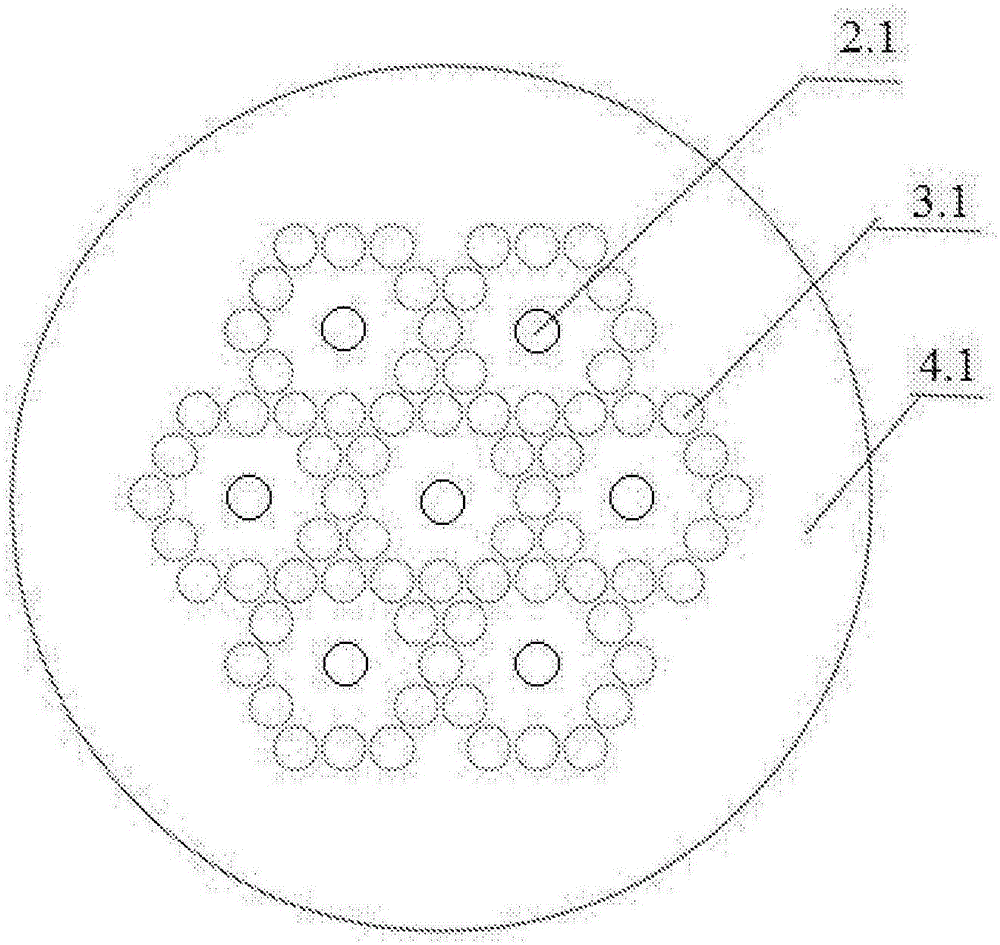
[0103] The microstructured multi-core optical fiber according to the invention comprises microstructured regions in which are embedded fundamental units, each of them comprising a core of doped silica glass with air-filled longitudinal holes surrounding it , (further, the pores) are located in a matrix of silica glass.

[0104] For a light wavelength of λ = 1550 nm, the difference between the refractive indices of the core material and cladding (outer and inner) corresponds to Δ = 5.2 10 -3 ±0.5·10 -3 .

[0105] The base unit is characterized by a D2 core diameter, a D3 pore diameter and a lattice constant Λ corresponding to the distance between the centers of adjacent pores. The center of the hole is positioned on the vertices and midpoints of the sides of the hexagon, the center of which is represented by the core; the length of the side c of the hexagon formed by the axis of the hole is equal to twice the lattice constant Λ. The base units juxtaposed within the microstru...


PUM


Abstract

Microstructured multicore optical fibre with a microstructure area, in which, at least two basic cells are embedded, where each of them contains a core, preferably made of glass, specifically including doped silica glass or polymer, together with the surrounding it longitudinal areas with lower refraction index vs. that of the cladding, which areas may adopt the shape of holes, filled with gas, in particular with the air or a fluid or a polymer or spaces of another glass with doping allowing to reduce refractive index(further referred to as holes), embedded in a matrix of glass, in particular of silica glass or polymer. The refraction index of the holes is decreased vs. that of the matrix of glass, in particular of silica glass or polymer. The basic cell is characterised by the diameter of D2 core, the diameter of D3 core and the distance between adjacent holes, corresponding to lattice constant. The centres of the holes are localised on the vertices and the middle points of the sides of the hexagon, the centre of which is designated by the core; the length of side c of the hexagon, created by the centres of holes, is equal to the preferably doubled lattice constant. The juxtaposed, at least, two basic cells are surrounded by the cladding, preferably made of glass, in particular of silica glass or polymer. Device for addressing cores of the multicore optical fibre, characteristic in that it contains single-core, single-mode optical fibres, with parallel layout in the capillary, (further referred to as single-mode optical fibres), in the number, corresponding to the number of the cores of the multicore optical fibre, while the capillary with single-mode optical fibres is connected with the multicore optical fibre, e.g., the microstructured optical fibre, according to this invention, while the cross-sections of the optical fibres in the capillary and the cross- section of the multicore optical fibre are parallel in their configuration. The fabrication method of the device for addressing cores consists in: 1. an analysis of the structure of multicore optical fibre and determination of the number of cores of the multicore optical fibre, the diameter of cores and the distances among them, 2. measurement of the diameters of the cores and of the claddings of single-mode optical fibres, with which the multicore optical fibre is connected, and the scale of tapering of the single-mode optical fibres is deteremined, 3. removal of the cladding of single-mode optical fibres and cleaning their surface, 4. etching, preferably with hydrofluoric acid, the exposed and cleaned fragments of the single-mode optical fibres, so that after their possible tapering and mutual reassembly, the alignment of the cores of the multicore optical fibre was possible with the cores of the single-mode optical fibre, 5. tapering of single-mode optical fibres, according to the calculated scale of tapering, allowing to achieve the diameters of their cores equal to the dimensions of the diameters of the cores of the multicore optical fibre (provided its preferable), 6. preparation of a capillary by its tapering to the size, allowing for insertion of single- mode optical fibres and glass rods, so that the inserted element shad no freedom of movement or that their movement was limited, 7. laying of single-mode optical fibres and glass rods in the capillary, 8. tapering and clamping of the laid and spliced structure in the capillary by its heating and tensing, while, if it is necessary, the multicore optical fibre is also tapered, 9. cleaving the capillary with the laid and spliced structure under right angle to the axis of the longitudinal capillary, preferably with a cleaver for optical fibres with various outer diameters and internal structures, with a possibility of controlled stretching of the fibre, preferably the capillary surface is polished, together with structure, laid in the capillary, 10. cleaving the multicore optical fibre and preferably polishing its surface, 11. orientation of the capillary vs. the multicore optical fibre, together with the structure, laid and welded in its inside, 12. connection of the multicore optical fibre with the capillary and the structure in its inside by means of any disclosed technology, preferably by splicing.

Description

technical field [0001] The subject matter of the present invention is a microstructured multicore optical fiber (MMOF) and a method of manufacturing a device for independent processing of the core of a microstructured multicore optical fiber. Background technique [0002] The introduction of optical fiber into telecommunication systems has resulted in a considerable increase in the availability of information transfer. Due to the rapidly increasing demand for ultra-high capacity levels of transmission channels, reaching 10 terabits / s per fiber, it seems necessary to replace the conventional, currently used, single-mode fiber of some sort with a breakthrough. Hitherto techniques of multiplexing (eg, in time, wavelength, polarization and other domains) simply cannot satisfactorily meet the exponential increase in transmission band requirements. A solution is introduced through space-division multiplexing (SDM) technology using multi-core fibers. SDM has been implemented in m...

Claims


Application Information

Patent Timeline
IPC IPC(8): G02B6/02
CPCG02B6/02042G02B6/02338G02B6/02357G02B6/02366H01S3/1608C03C25/68
Inventor 托马斯·纳什洛夫斯基卡塔兹娜乔安娜·帕夫利克兹比格涅夫·豪迪斯基迈克尔·穆拉夫斯基塔德乌什·特尼德仁达马芮克·纳皮莱拉安娜·兹罗威兹卢克·奥斯特洛夫斯基马太·司鲁维科夫斯基卢克·苏佐斯基维兹迈克尔·斯兹曼基卡罗尔·施特平
Owner 信息技术有限公司
Why Eureka
Eureka Blog
Learn More