Eureka AIR delivers breakthrough ideas for toughest innovation challenges, trusted by R&D personnel around the world.

Pipe orifice mould-withdrawing tool for container

A nozzle and tooling technology, which is applied in the field of container nozzle drafting tooling, to achieve the effect of not being easy to wear and deform, and reducing labor intensity

Inactive Publication Date: 2017-01-04
FEATURE-TEC (WUXI) FILTRATION TECH CO LTD
View PDF9 Cites 0 Cited by
  • Summary
  • Abstract
  • Description
  • Claims
  • Application Information

AI Technical Summary

Problems solved by technology

[0013] Aiming at the problems encountered in the actual manufacturing of sanitary equipment, the present invention provides a new nozzle forming process, which solves the manufacturing problems arising in the above-mentioned manufacturing; use the drafting tool to pull the pipe at the nozzle of the equipment to form a draft hole , so that the nozzle and the cylinder are butt-connected, and the pipe-drawing part is naturally formed by the action of the upper and lower dies of the draft tooling, leaving no hygienic dead corners; the use of this connection method also improves the welding and polishing problems in subsequent manufacturing, and the connection Plasma welding or laser welding can be used for the butt ring seam, which not only ensures the full penetration of the weld seam, but also ensures the shrinkage and deformation of the weld seam. The inner surface is ground and polished; the design of the draft tooling is to meet the connection requirements of the equipment. Integrating the actual mass production operation, we use the hydraulic mold to pull the equipment; the cylinder is stretched or sealed by the hydraulic device. The upper mold of the nozzle on the head, the upper mold is lowered, the round hole in the center of the workpiece opening continues to expand, the material under the upper mold is transferred to the side and completely attached to the side wall of the lower mold, and the edge of the hole of the workpiece is played by the cooperation of the upper and lower molds. Flip out the straight edge erected at a certain angle

Method used


Image

  • Pipe orifice mould-withdrawing tool for container
  • Pipe orifice mould-withdrawing tool for container

Examples


Embodiment 1

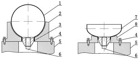
[0028] Embodiment 1: Place the lower mold for tube extubation and the part 2 on the mold placement platform 4 for assembly and positioning, place the draft cylinder 1 on the lower mold for tube extubation 2 for positioning, install the upper mold for extubation 3, and simultaneously The hydraulic machine connecting screw 5 is tightened and fixed; start the hydraulic machine to drive the hydraulic machine connecting screw 5, so that the drawing upper die 3 descends, and the round hole in the center of the hole in the part drawing cylinder 1 continues to expand, and the material under the drawing upper die 3 faces sideways Transfer to the side wall of the lower mold 2 that is completely close to the cylinder body, and the edge of the hole of the workpiece will turn out the vertical straight edge under the cooperation of the upper and lower molds.

Embodiment 2

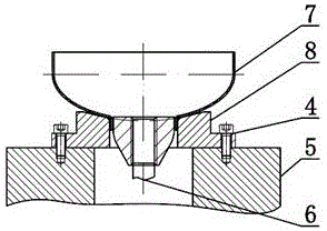
[0029] Embodiment 2: Assembling and positioning the lower mold 7 for pulling out the cap and the mold placement platform 4, placing the drawing head 6 on the lower die 7 for pulling out the pipe for positioning, installing the upper die 3 for pulling out the pipe, and tightening it with the connecting screw 5 of the hydraulic press Fixed; start the hydraulic machine to drive the hydraulic machine to connect the screw 5, so that the drawing upper die 3 descends, and the round hole in the center of the opening of the piece drawing die head 1 continues to expand, and the material under the drawing upper die 3 is transferred to the side to fully abut The side wall of the lower mold 7 is drawn out of the head, and the edge of the hole of the workpiece is turned out of the vertical straight edge under the cooperation of the upper and lower molds.


PUM


Abstract

The invention relates to a pipe orifice mould-withdrawing tool for a container. The tool is composed of a mould-withdrawing barrel, a barrel pipe-withdrawing lower mould, a pipe-withdrawing upper mould, inner hexagonal screws, mould placing platforms, a hydraulic machine connecting screw rod, a mould-withdrawing seal head and a seal head pipe-withdrawing lower mould. The tool is suitable for pipe orifice mould-withdrawing mould forming production of sanitary grade equipment, and belongs to the technical field of an innovative process of manufacturing the sanitary grade equipment. A reasonable mould operating mode is as follows: a mould is driven hydraulically; a workpiece is placed on a hydraulic platform by a worker, upper and lower moulds are assembled, a hydraulic device is started, and a step of withdrawing the mould can be finished only by an operation of a single worker, so that the labor intensity of the worker is alleviated.

Description

technical field [0001] The innovative design and a nozzle draft tooling for containers are suitable for nozzle draft molding production of sanitary equipment, specifically a nozzle draft tooling for containers, which belongs to the technical field of sanitary equipment manufacturing innovative technology. Background technique [0002] Sanitary filters belong to the scope of clean production process equipment, and are one of the important equipment used for filtration and separation in the food, drug and beverage industries. With the development of science and technology and economy, food and pharmaceutical industries must ensure To improve product quality, improve production efficiency, and reduce management costs, sanitary filters are used. At the same time, the structure of sanitary filters is becoming more simple, easy to clean and practical; the structural characteristics of existing sanitary equipment are : [0003] 1) There are no defects such as dents, creases, crack...

Claims


Application Information

Patent Timeline
IPC IPC(8): B21D19/08B21D37/10
CPCB21D19/088B21D37/10
Inventor 何向阳苏林杰樊丽琴
Owner FEATURE-TEC (WUXI) FILTRATION TECH CO LTD
Why Eureka
Eureka Blog
Learn More