Laser cutting machine

A technology of laser cutting machine and laser knife, applied in the field of cutting device and laser cutting machine, can solve the problems of waste, easy overheating of the cutter head, difficult installation and transportation, etc., to achieve the effect of avoiding waste

Inactive Publication Date: 2017-01-04
安徽联亚智能装备制造有限公司
View PDF9 Cites 6 Cited by
  • Summary
  • Abstract
  • Description
  • Claims
  • Application Information

AI Technical Summary

Problems solved by technology

[0003] In the current laser cutting machine, there is a lack of protection and purification devices for the cutting head, the cutting head is easy to overheat, and the auxiliary gas lacks a control device when it is introduced, which is easy to cause waste, and the overall structure is large, which is not easy to install and transport

Method used


Image

  • Laser cutting machine
  • Laser cutting machine
  • Laser cutting machine

Examples


Embodiment 1

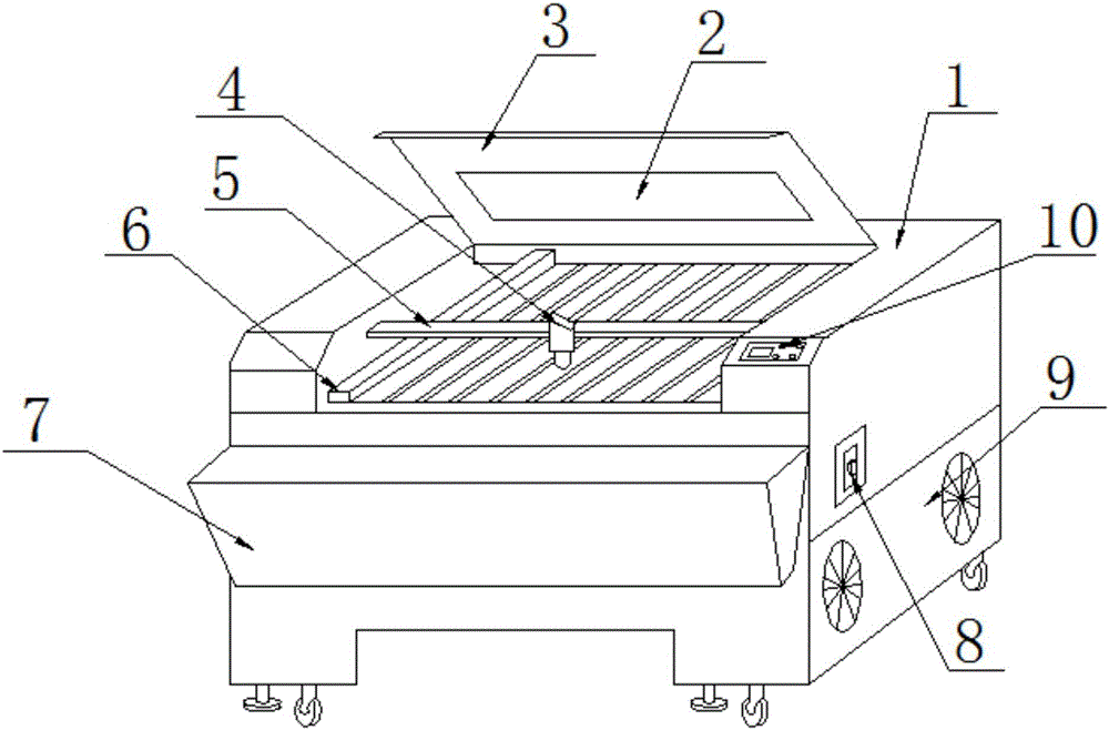
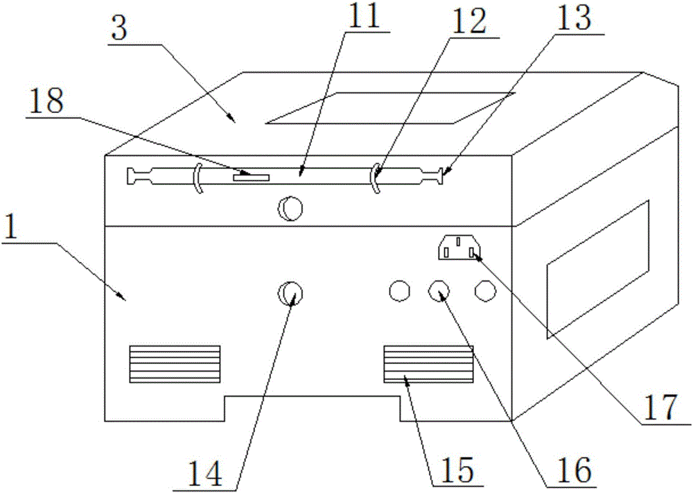
[0020] Such as figure 1 , figure 2 with image 3 As shown, a laser cutting machine provided in this embodiment includes a chassis 1, a transverse guide rail 5, a longitudinal guide rail 6, a drive electric box 15, and a laser cutter head 4. The top center of the chassis 1 is connected to the cover plate 3 through a rotating shaft, and The area of ​​the cover plate 3 is the same as the area of ​​the groove of the chassis 1; the surface of the cover plate 3 is provided with an observation window 2, which can observe the operating conditions inside the device; the surface of the chassis 1 is provided with a control panel 10 near the exit. , to realize automatic operation and easy to use; the side wall of the chassis 1 is provided with a brake switch 8, which can brake with one button and increase the safety performance; the bottom of the brake switch 8 is provided with a cooling fan 9, and the cooling fan 9 is fixed on the bottom of the chassis 1 Inside, the heat accumulated i...

Embodiment 2

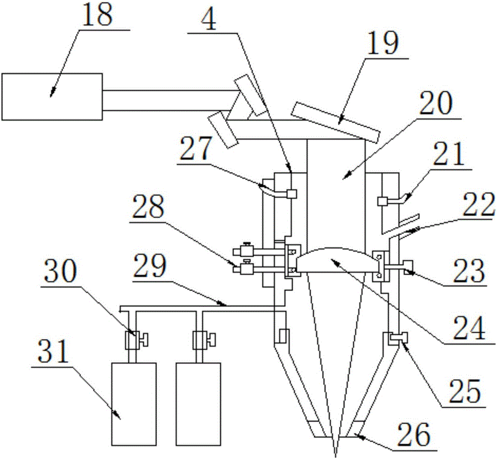
[0023] Such as figure 1 , figure 2 with Figure 4As shown, the general structure of the laser cutting machine provided in this embodiment is consistent with that of Embodiment 1, but in order to speed up the work efficiency, wherein the nozzle 26 is a cylindrical nozzle, the laser cutting machine provided in this embodiment, It includes a chassis 1, a horizontal guide rail 5, a longitudinal guide rail 6, a drive electric box 15, and a laser cutter head 4. The top center of the chassis 1 is connected to the cover plate 3 through a rotating shaft, and the area of ​​the cover plate 3 is the same as the area of ​​the groove of the chassis 1. The surface of the cover plate 3 is provided with an observation window 2, which can observe the operating conditions inside the device; the surface of the cabinet 1 is provided with a control panel 10 near the exit, which realizes automatic operation and is easy to use; the side wall of the cabinet 1 The brake switch 8 is set, which can br...


PUM


Abstract

The invention discloses a laser cutting machine. The laser cutting machine comprises a case, an observation window, a cover plate, a laser tool bit, a transverse guide rail, a longitudinal guide rail, a collecting hopper, a brake switch, a cooling fan, an operation panel, a laser tube, clamp rings, laser outlets, induced draft ports, driving electricity boxes, external connecting holes, a power plug, a laser generator, a reflecting mirror, a laser beam, a smoke sensor, a cooling gas pipeline, a first adjusting knob, a lens, a second adjusting knob, a nozzle, an optical sensor, a cooling water pipeline, an auxiliary gas pipeline, solenoid valves and auxiliary gas cylinders. The laser cutting machine has the beneficial effects as follows: the laser cutting machine has the function of stopping machining when the lens is burned out, and the optical sensor is mounted above the machining lens, can be used for measuring the light quantity at a machined part and also has functions of realizing focusing, preventing over-burning and the like; and the cooling gas pipeline is arranged, and nitrogen or dry air which can be sprayed to the lens from the upper side of the lens can have a cooling effect and is also applied to optical path clean-keeping.

Description

technical field [0001] The invention relates to a cutting device, in particular to a laser cutting machine, which belongs to the technical field of laser equipment application. Background technique [0002] The application of laser cutting machines in the industrial field continues to grow and has achieved great success, especially in the manufacturing industry, where most of the laser cutting machines in the industrial field are concentrated. Compared with other cutters, it has many advantages. For example, its high speed, high precision, high adaptability, etc., have solved many problems that cannot be solved by conventional methods in industrial production, and greatly reduced the labor intensity of workers. [0003] In the current laser cutting machine, there is no protection and purification device for the cutting head, the cutting head is easy to overheat, and the auxiliary gas lacks a control device when it is introduced, which is easy to cause waste, and the overall ...

Claims


Application Information

Patent Timeline
Patent Type & Authority Applications(China)
IPC IPC(8): B23K26/38B23K26/14B23K26/70
CPCB23K26/147B23K26/38B23K26/702
Inventor 许齐宝李世金于珺黄长连陈达兵
Owner 安徽联亚智能装备制造有限公司
Why Eureka
Try Eureka