Supercharge Your Innovation With Domain-Expert AI Agents!

Sand blasting machine

A sandblasting machine and sandblasting technology, applied in the field of sandblasting machines, can solve the problems of the negative impact of NVH on the whole vehicle, the unstable sandblasting quality, and the increase of the axial derivative force, so as to achieve stable sandblasting quality and high automation strength. , the effect of improving production efficiency

Active Publication Date: 2017-01-04
耐世特凌云驱动系统(涿州)有限公司
View PDF11 Cites 6 Cited by
  • Summary
  • Abstract
  • Description
  • Claims
  • Application Information

AI Technical Summary

Problems solved by technology

[0002] After heat treatment in the inner cavity of the three-pin shaft cylindrical shell, a layer of oxide skin will be formed on the surface, and the outer ring of the bearing frame will cause the oxide skin to fall off when sliding in the inner cavity of the three-pin shaft cylindrical shell, thereby increasing the axial derived force and affecting the Negative impact on vehicle NVH
Existing standard sandblasting machine comprises sandblasting chamber, abrasive liquid box, sandblasting pump and spray gun; The sandblasting of the workpiece has low sandblasting efficiency, and the sandblasting time for each piece is 80 seconds; the labor intensity is high, and the operator needs to manually control the rotation of the workpiece and the angle of the spray gun; manually controlling the rotation of the workpiece and the angle of the spray gun will cause the workpiece to be sprayed. The material removed after sanding is not uniform, which may easily cause the size to be out of tolerance and the sandblasting quality is unstable

Method used


Image

  • Sand blasting machine
  • Sand blasting machine
  • Sand blasting machine

Examples


Embodiment Construction

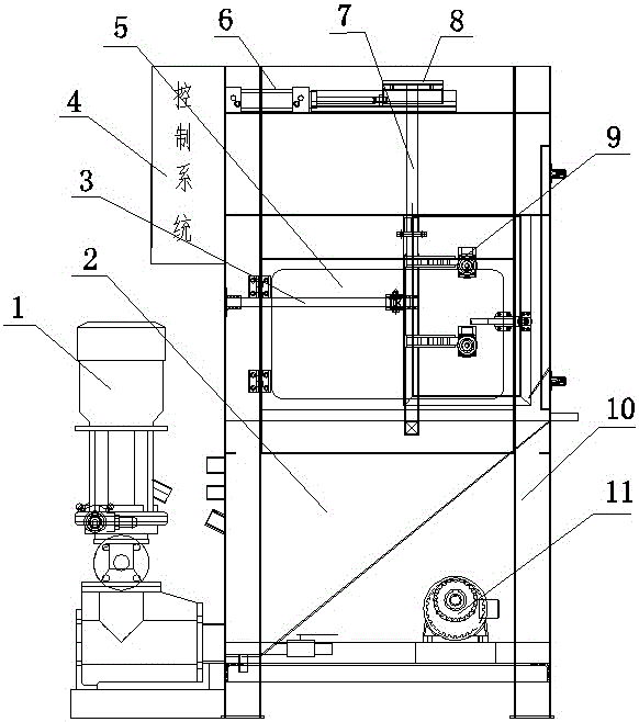
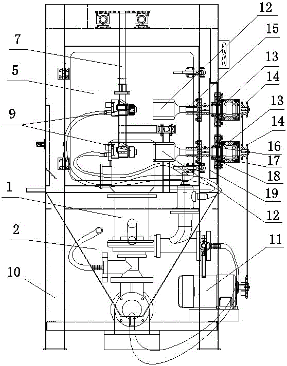
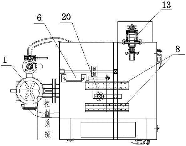
[0015] The present invention will be further described in detail below in conjunction with the accompanying drawings and specific embodiments.

[0016] Such as figure 1 , figure 2 and image 3 As shown, the present embodiment includes a frame 10, a sandblasting chamber 5, a grinding fluid box 2, a workpiece rotating mechanism, a sandblasting system and a control system. The sandblasting chamber 5 is fixed on the upper end of the frame 10, and the grinding fluid box 2 is fixed on the lower end of the frame 10, just below the sandblasting chamber 5. The workpiece rotating mechanism includes a reduction motor 11 fixed on the frame 10, and 2 (1, 3, 4, etc. can also be selected according to needs, but 1 is inefficient) rotating tooling. The rear end of each rotary tool is rotatably fixed on the chamber wall of the sandblasting chamber 5, and its front end is fixed with a clamp 15; The rear end of the rotary tool is rotatably fixed on the wall of the sandblasting chamber 5, and...


PUM


Abstract

The invention discloses a sand blasting machine. The sand blasting machine comprises a rack, a sand blasting chamber, a grinding fluid box, a speed reduction motor, workpiece rotating mechanisms of one or multiple rotating tools, a sand blasting system and a control system; the rear end of each rotating tool is rotatably fixed to the wall of the sand blasting chamber, clamps are fixed to the front ends of the rotating tools, and the rear ends of the rotating tools are connected with the speed reduction motor; the clamps are outer spline shafts or inner spline hollow shafts in micro-clearance fit with inner splines or outer splines on a shaft of a three-pin-shaft cylindrical shell, one or multiple spraying guns are connected to a liquid outlet of a sand blasting pump through hoses, the spraying guns are fixed to spraying gun fixing rods, and the centers of openings of the spraying guns right face the center lines of the clamps; two normally-open contacts of a relay control starting and stopping of the speed reduction motor and stretching out and shrinking of an air cylinder piston rod, and the control system controls a relay coil power source to be on and off. The sand blasting machine is high in sand blasting efficiency, stable in sand blasting quality, high in machined workpiece quality, high in production efficiency, high in automation strength and capable of reducing labor intensity of operators.

Description

technical field [0001] The invention relates to a sandblasting machine, in particular to a sandblasting machine for the inner cavity of a three-pin shaft cylindrical shell. Background technique [0002] After heat treatment in the inner cavity of the three-pin shaft cylindrical shell, a layer of oxide skin will be formed on the surface, and the outer ring of the bearing frame will cause the oxide skin to fall off when sliding in the inner cavity of the three-pin shaft cylindrical shell, thereby increasing the axial derived force and affecting the Negative impact on vehicle NVH. In order to eliminate this effect, the oxide scale in the cylindrical shell must be removed. After process verification, the sandblasting process can be selected to remove the oxide skin in the inner cavity, and remove the oil, iron filings and other impurities in the inner cavity, thereby improving the cleanliness, strength and roughness of the inner cavity. Existing standard sandblasting machine c...

Claims


Application Information

Patent Timeline
IPC IPC(8): B24C3/32B24C3/16B24C5/02B24C9/00B24C1/08
CPCB24C1/086B24C3/16B24C3/325B24C5/02B24C9/00
Inventor 刘代江戴小科侯剑斌马赛耿旭
Owner 耐世特凌云驱动系统(涿州)有限公司
Features
  • R&D
  • Intellectual Property
  • Life Sciences
  • Materials
  • Tech Scout
  • Unparalleled Data Quality
  • Higher Quality Content
  • 60% Fewer Hallucinations
Learn More