

Casting assembly line and method for mutual inductors
A pouring method and technology of transformers, applied in chemical instruments and methods, cleaning methods using gas flow, inductors, etc., can solve the problems of not having the cleaning function of the pouring system, the inability to automatically control the pouring amount, and the low automation application. Achieve the effect of improving irrigation efficiency and product qualification rate, simple structure and high degree of automation
- Summary
- Abstract
- Description
- Claims
- Application Information
AI Technical Summary
Problems solved by technology
Method used
Image

Examples
Embodiment 1
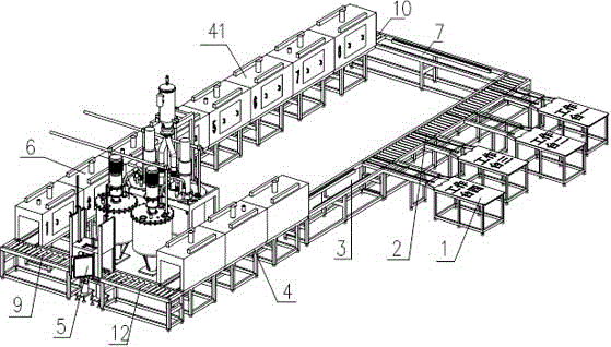
[0063] Such as figure 1 As shown, a transformer pouring line of the present invention includes an operation table 1, an operation table drum line 2, a drying buffer area 3, a pre-baking area 4, a pouring chamber 5, a curing area 6 and a demoulding buffer area 7, a plurality of The operation table 1 is connected to the outside of the operation table drum line 2, and the transformer is molded through the operation table 1 and then transferred to the operation table drum line 2; the operation table drum line 2 is connected to the drying buffer 3, and through the drying buffer The beat control system 8 set on 3 transmits the molded transformer into the pre-baking zone 4 according to the set beat, and the pre-baked zone (4) transmits the molded transformer into the pouring chamber through the connected mold feeding roller line 12, after pouring The molded transformer is transported into the curing area 6 through the ejection roller line 9 connected with the pouring chamber, and the...
Embodiment 2
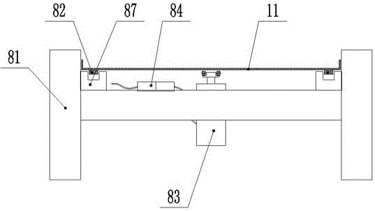
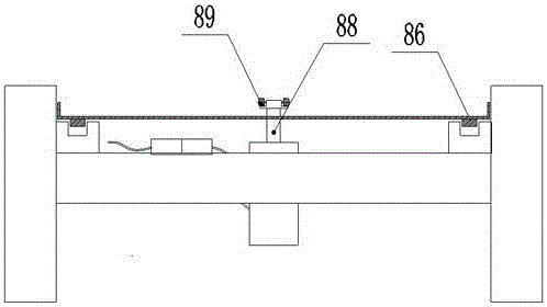
[0065] Such as Figure 2-5 As shown, the present invention is a transformer pouring line. On the basis of Embodiment 1, the beat control system 8 includes a transmission platform 81, a conveyor belt 82, a lifting cylinder device 83 and a photoelectric sensor controller 84. The transmission platform 81 Conveyor belts 82 are arranged on both sides, and the middle part of the transmission platform 81 between the two conveyor belts 82 is provided with a lifting cylinder device 83. The photoelectric sensor controller 84 controls and connects the lifting cylinder device 83 through photoelectric induction. The lifting cylinder device 83 adopts AirTAC SC125*25 cylinder can also be used cylinder model: SUMC SDA63-25.
[0066] The conveyor belt 82 is a chain 86, and the chain 86 is arranged in a concave conveyor groove 87. The cylinder arm 88 top of lifting cylinder device 83 is provided with pulley assembly 89, and pulley assembly 89 can adopt two coaxial pulleys to be arranged on cyl...
Embodiment 3
[0072] Such as Figure 6 and Figure 7As shown, a transformer casting line of the present invention, on the basis of Embodiment 1, the casting chamber 5 is provided with a transformer vacuum filling control system, and the transformer vacuum filling control system includes A discharge valve 511, B discharge valve Valve 512, static mixer assembly 513 and filling nozzle 514, A discharge valve 511 and B discharge valve 512 are respectively connected to static mixer assembly 513, A discharge valve 511 is connected to material tank through A sampling valve 516, The B discharge valve 511 is connected to the material tank through the B sampling valve 517, the static mixer assembly 513 is connected to the filling nozzle 514, and a distance sensing device 515 is arranged on one side of the filling nozzle 514, and the distance sensing device 515 is connected to the 51A through the controller 519 respectively. Discharge valve 1 and B discharge valve 512 are controlled and connected, and...
PUM
 Abstract
Description
Claims
Application Information