Forming window for high-speed continuous photocuring 3D printing

A 3D printing and 3D printer technology, which is applied in the field of high-speed continuous light-curing 3D printing forming windows, can solve the problem that oxygen-permeable and ultraviolet-permeable Teflon materials are expensive, and it is difficult to realize large-scale and high-efficiency manufacturing of solid parts. Rapid supply of resin materials and other issues to achieve the effect of expanding the range of process use, improving printing efficiency, and increasing the size

Active Publication Date: 2017-01-04
QINGDAO TECHNOLOGICAL UNIVERSITY
View PDF7 Cites 19 Cited by
  • Summary
  • Abstract
  • Description
  • Claims
  • Application Information

AI Technical Summary

Problems solved by technology

However, this point-by-point scanning photocuring method has the following disadvantages: low forming efficiency (about 8~12x 10 4 mm 3 / h); there is a large shrinkage during curing, and the workpiece is warped
However, the forming window of the CLIP process faces some shortcomings and limitations:
[0005] (1) The oxygen-permeable and UV-permeable Teflon materials used are very expensive and require special manufacturing processes
[0006] (2) When the photosensitive resin undergoes a cross-linking and curing reaction, a large amount of heat will be released, which will cause the temperature of the beam irradiation area to rise. Reduced, affecting light efficiency and quality of formed parts
[0007] (3) A large number of heat sources are released by CLIP high-speed continuous curing. The existing solutions cannot discharge and release the heat in a timely and effective manner. Therefore, the current forming workpieces of the CLIP process are limited to printing of smaller-sized objects (the heat generated by small-sized parts is relatively small. less, the heat exchange is relatively easy to remove)
[0008] (4) For high-speed printing of photosensitive resin, when the separation speed reaches a certain amount, the biggest constraint is the reflow speed of the resin, especially when the viscosity of the resin is relatively high, it is more difficult to handle
[0009] Therefore, for the printing of large-sized objects, processes such as CLIP still face the problem of rapid replenishment of resin materials consumed by the liquid surface in the bottom dead zone and the solidified liquid surface.
Therefore, the existing continuous photocuring process (such as CLIP) is only suitable for printing small-sized objects, and the shape of typical printed parts is mostly limited to some hollow structures, which makes it difficult to achieve high-efficiency printing of large-sized and solid parts; and printing speed and Further improvements in quality are limited

Method used


Image

  • Forming window for high-speed continuous photocuring 3D printing
  • Forming window for high-speed continuous photocuring 3D printing
  • Forming window for high-speed continuous photocuring 3D printing

Examples


Embodiment 1

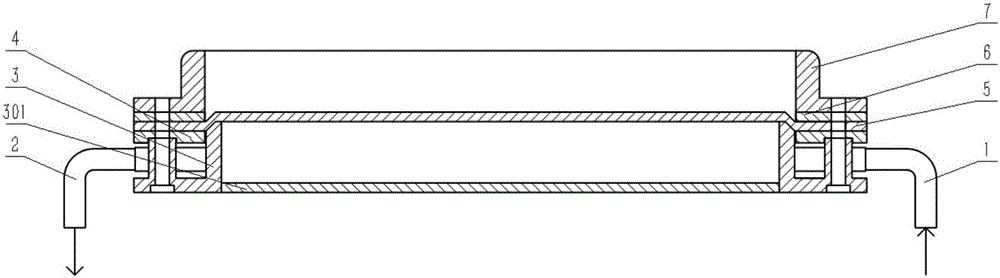
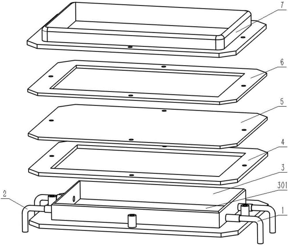
[0063] figure 1 It is a schematic diagram of the structural principle of the forming window for high-speed continuous photocuring 3D printing in Example 1 of the present invention, figure 2 It is a schematic exploded view of the forming window for high-speed continuous photocuring 3D printing in Example 1 of the present invention. Embodiment 1 The molding window includes: cooling air intake pipeline 1, cooling air outlet pipeline 2, oxygen supply cooling chamber 3, transparent quartz plate 301, pressure plate 4, composite oxygen-enriched membrane 5, sealing gasket 6, and liquid storage tank 7. The oxygen supply cooling chamber 3, the pressing plate 4, the composite oxygen-enriched membrane 5, the sealing gasket 6, and the liquid storage tank 7 are provided with holes through up and down, wherein the oxygen supply cooling chamber 3, the pressing plate 4, and the upper holes of the liquid storage tank 7 are Threaded holes, one side of the oxygen supply cooling chamber 3 has a ...

Embodiment 2

[0072] Example 2 The schematic diagram of the structure of the forming window for high-speed continuous light-curing 3D printing is as follows Figure 4As shown, on the basis of the molding window in Embodiment 1, a liquid level auxiliary pressure application module is added, including the upper chamber 10 of the chassis and the pressurized intake pipeline 11 . The printing device is divided into upper and lower chambers with the middle partition of the fixed window box as the boundary. The upper chamber 10 of the chassis has good airtightness, and the oil-free air compressor increases the gas pressure of the upper chamber through the pressurized intake pipeline 11 . During printing, high-pressure gas exerts pressure on the liquid surface of photosensitive resin to accelerate the flow of resin to the "dead zone" and curing area, and realize rapid resin reflow and replenishment.

Embodiment 3

[0074] As another embodiment, the cooling outlet pipeline 2 is connected to a vacuum pump, and the vacuum pump pumps air to promote the gas flow in the closed chamber formed by the oxygen supply cooling chamber 3 and the composite oxygen-enriched membrane 5, thereby improving the cooling efficiency.


PUM

PropertyMeasurementUnit
pore sizeaaaaaaaaaa
thicknessaaaaaaaaaa
thicknessaaaaaaaaaa

Abstract

The invention discloses a forming window for high-speed continuous photocuring 3D printing. The forming window applied to a photocuring 3D printer comprises a window box and an oxygen supply cooling module. The photocuring 3D printer is divided into an upper cavity and a lower cavity through a middle partition. The window box and the oxygen supply cooling module are arranged in the upper cavity of the case of the photocuring 3D printer. The window box and the oxygen supply cooling module are fixedly mounted on the middle partition in a combined manner. Two ends of an oxygen supply cooling chamber are respectively connected with a cooling gas inlet pipeline and a cooling gas outlet pipeline, and the oxygen supply cooling chamber, the o cooling gas inlet pipeline and the cooling gas outlet pipeline form the oxygen supply cooling module. The forming window has the advantages that low-cost and efficient continuous printing of large-size optional-shape parts can be achieved, the forming window is wide in applicable materials, the precision and quality of the printed parts are high, the printed parts are good in consistency, and process stability and reliability are achieved. In addition, the forming window is high in industrial application value and applicable to a desktop-level 3D printer and industrial 3D printing.

Description

technical field [0001] The invention relates to the technical fields of additive manufacturing and 3D printing, in particular to a forming window for high-speed continuous photocuring 3D printing. Background technique [0002] Stereolithography is the earliest, most mature, and most widely used additive manufacturing (3D printing) technology. After nearly 30 years of development, it has developed from the initial stereolithography (SL) to Many new processes, such as Microstereolithography, Integral SL, Projection Microstereolithography, Digital Light Processing (DLP) 3D printing, Continuous Liquid Interface Production , CLIP), two-photon polymerization laser direct writing 3D printing, etc. [0003] Traditional stereolithography is to use laser galvanometer or mask technology to control the illumination area, so that the resin is cured layer by layer in the controllable illumination area, and a three-dimensional solid model is generated after layer-by-layer curing and stack...

Claims


Application Information

Patent Timeline
Patent Type & Authority Applications(China)
IPC IPC(8): B29C67/00B33Y30/00B33Y40/00B33Y50/02B33Y10/00
CPCB33Y10/00B33Y30/00B33Y40/00B33Y50/02
Inventor 钱垒兰红波
Owner QINGDAO TECHNOLOGICAL UNIVERSITY
Why Eureka
Try Eureka