Hydraulic walking mechanism for tunnel lining working jumbo and control method

A technology for a template trolley and a traveling mechanism, which is applied to a transmission device with a rotating prime mover, etc., can solve the problems of reducing the walking reliability of the traveling device, unable to realize synchronous control, unable to realize continuous walking, etc., and achieves a small moment of inertia, The effect of good low speed stability and short start and stop times

Active Publication Date: 2017-01-04
NANTONG TIEJUN MACHINERY CO LTD
View PDF7 Cites 4 Cited by
  • Summary
  • Abstract
  • Description
  • Claims
  • Application Information

AI Technical Summary

Problems solved by technology

[0006] From the above search, it can be seen that although Patent Announcement 1 can realize the continuous walking of the tunnel lining trolley and even realize the synchronous control of walking, the traveling mechanism is relatively complicated, which reduces the traveling reliability of the traveling device. At the same time, the traveling track must be a rectangular sawtooth rail. Brings difficulties to the processing of the track
Patent announcement 2 Although the running of the tunnel lining trolley does not require a track, which saves the man-hours of track laying, it cannot achieve continuous walking, the walking efficiency is low, and synchronous control cannot be realized at the same time

Method used


Image

  • Hydraulic walking mechanism for tunnel lining working jumbo and control method
  • Hydraulic walking mechanism for tunnel lining working jumbo and control method
  • Hydraulic walking mechanism for tunnel lining working jumbo and control method

Examples


Embodiment Construction

[0025] The preferred technical solutions of the present invention will be described in detail below in conjunction with the accompanying drawings, but the protection scope of the present invention is not limited thereto.

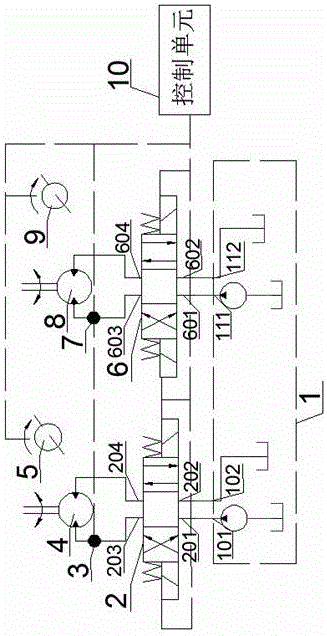
[0026] The invention provides a hydraulic traveling mechanism and control method for a tunnel lining formwork trolley, and designs a hydraulic control circuit from a hydraulic pump station to a hydraulic motor and synchronous control of the left and right sides of the trolley walking frame in detail.

[0027] figure 1 Shown is the hydraulic principle structure diagram of the hydraulic traveling mechanism, including hydraulic pump station 1, proportional reversing valve I2, oil pressure sensor I3, hydraulic motor I4, encoder I5, proportional reversing valve II6, oil pressure sensor II7, hydraulic motor II8, encoder II9 and control unit 10, the hydraulic pump station 1, proportional reversing valve I2 and hydraulic motor I4 are sequentially connected through h...


PUM


Abstract

The invention discloses a hydraulic walking mechanism for a tunnel lining working jumbo and a control method. Hydraulic motors on the left side and the right side of a hydraulic oil driver of a hydraulic pump station are connected and then connected with drive wheel axles on the left side and the right side through couplers, so the jumbo is driven to walk; in order to make the jumbo advance or retreat, bidirectional quantitative hydraulic motors are adopted as the hydraulic motors, and the hydraulic motors are rotated forward or backward by changing the flowing direction of hydraulic oil in the hydraulic motors; in order to synchronously control a left drive wheel and a right drive wheel of the jumbo, through signals of pressure sensors between a proportional electromagnetic valve and the hydraulic motors and encoders on driven wheels, the proportional electromagnetic valve is controlled so as to control the rotating speed of the hydraulic motors; a drive mechanism adopted by the hydraulic walking mechanism is simple in structure, high in reliability and convenient to control.

Description

technical field [0001] The invention relates to the field of driving and control of a tunnel lining formwork trolley, in particular to a hydraulic traveling mechanism and a control method for a tunnel lining formwork trolley. Background technique [0002] At present, the walking mechanism of the track-type tunnel lining formwork trolley is generally driven by a motor, and the power is transmitted to the driving wheels on both sides through the motor installed on both sides through the reduction mechanism and the chain. In order to obtain a large driving force, a worm gear reducer is usually installed. . There are more transmission parts in the whole transmission process, which reduces the transmission reliability. At the same time, the transmission efficiency of the worm gear reducer is also relatively low; especially when the left and right driving wheels are not synchronized, the chain on the side with the larger driving force is easy to Fracture occurs, which will affect...

Claims


Application Information

Patent Timeline
Patent Type & Authority Applications(China)
IPC IPC(8): B61C9/34
CPCB61C9/34
Inventor 朱忠银张少伟张杰韩江义商高高夏长高高翔夏卫东
Owner NANTONG TIEJUN MACHINERY CO LTD
Why Eureka
Try Eureka