Direct current magnetic leakage detecting system and method based on triggered acquisition mode

A collection mode and magnetic flux leakage detection technology, which is applied in the direction of material magnetic variables, railway vehicle shape measuring instruments, railway car body parts, etc., can solve the unfavorable processing of data packets, data loss, and the single magnetic flux leakage detection method cannot cover all speed ranges and other problems to achieve the effect of helping analysis and identification, improving utilization and ensuring integrity

Inactive Publication Date: 2017-01-04
NANJING UNIV OF AERONAUTICS & ASTRONAUTICS
View PDF7 Cites 16 Cited by
  • Summary
  • Abstract
  • Description
  • Claims
  • Application Information

AI Technical Summary

Problems solved by technology

[0004] Chinese patent application (application publication number: 104764799.A) discloses "a detection system and method combining AC and DC magnetic flux leakage technology", and proposes a method of combining DC magnetic flux leakage and AC magnetic flux leakage detection technology to overcome The problem that a single magnetic flux leakage detection method of DC or AC cannot cover the entire speed range
But this application has following defect: 1. this application is in DC detection system, and acquisition

Method used


Image

  • Direct current magnetic leakage detecting system and method based on triggered acquisition mode
  • Direct current magnetic leakage detecting system and method based on triggered acquisition mode
  • Direct current magnetic leakage detecting system and method based on triggered acquisition mode

Examples


Embodiment Construction

[0035] The present invention will be described in further detail below in conjunction with the accompanying drawings and embodiments.

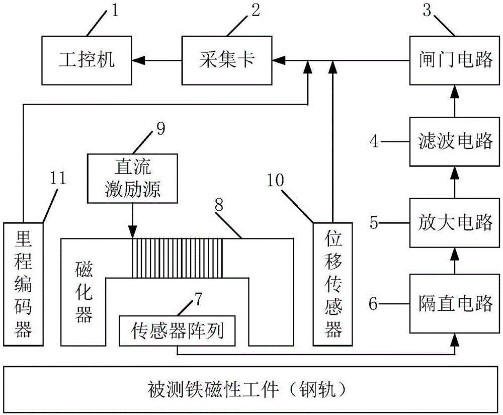
[0036] Such as figure 1 Shown is a system structure block diagram of an embodiment of the present invention. The system of the embodiment of the present invention includes an industrial computer 1 , an acquisition card 2 , a filter circuit 4 , an amplifier circuit 5 , a sensor array 7 , a magnetizer 8 , and a DC excitation source 9 .

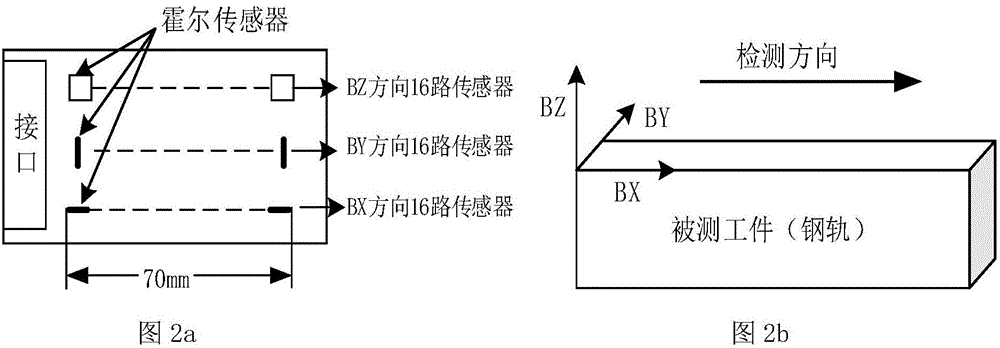
[0037] figure 2 is a schematic diagram of a sensor array according to an embodiment of the present invention. Such as figure 2 As shown, each rail is equipped with 48 Hall sensors, which are divided into 16 Hall sensors in the BX direction (radial direction of the rail, that is, the inspection direction), BY direction (horizontal direction of the rail), and BZ direction (perpendicular to the surface of the rail). , the length is 70mm, which can realize the coverage detection of the entire horizontal direct...


PUM


Abstract

The invention discloses a direct current magnetic leakage detecting system based on a triggered acquisition mode. The direct current magnetic leakage detecting system comprises a sensor array, a DC-block, an amplifying circuit, a filtering circuit, a triggering circuit, an acquisition card, and an industrial personal computer which are in serial connection sequentially, and also comprises a displacement sensor and a mileage encoder which are in serial connection with the triggering circuit sequentially, wherein the sensor array is provided with a 48-channel hall sensor, and every 16 channels are separately arranged in a radial routing inspection direction BX, a lateral direction BY and a direction BZ perpendicular to the surface of each steel rail; the acquisition card adopts a triggered acquisition mode, and a trigger signal of the acquisition card is provided by the triggering circuit; the triggering circuit is in series connection between the acquisition card and the filtering circuit, and performs threshold judging treatment on a 48-channel detecting voltage signal; the displacement sensor can measure a lift-off value between the sensor array and the surface of the measured steel rail; and the mileage encoder can acquire the routing inspection mileage of the railway steel rails. According to the direct current magnetic leakage detecting system disclosed by the invention, defect magnetic leakage detection can be performed under the condition with different routing inspection speeds, data is not liable to lose, the routing inspection mileage can be acquired and defects can be efficiently positioned.

Description

technical field [0001] The invention belongs to the technical field of dynamic testing and detection of railway rail defects, and relates to a DC magnetic flux leakage detection system in a triggering acquisition mode and a method thereof. Background technique [0002] With the great development of high-speed and heavy-duty railways, the degree of extrusion and stamping of online service rails has increased, and the probability of damage has also increased. The damage of high-speed railway rails is mainly caused by the contact fatigue between train wheel sets and rails, while the damage of heavy-duty railway rails is mainly caused by the plastic deformation and wear of rails, which poses a huge threat and severe challenge to train safety. At present, domestic and foreign railway rail testing mainly adopts the combination of large-scale high-speed flaw detection vehicle and low-speed hand-push flaw detection vehicle based on conventional ultrasonic testing technology and eddy...

Claims


Application Information

Patent Timeline
IPC IPC(8): B61K9/08G01N27/83
CPCB61K9/08G01N27/83
Inventor 王平朱兴俊徐维磊张浪白坚
Owner NANJING UNIV OF AERONAUTICS & ASTRONAUTICS
Why Eureka
Try Eureka