
Complex-hinge transformable trailing edge mechanism based on planar linkage closed-loop units

A flat-link, closed-loop technology, applied in wing adjustment and other directions, can solve the problems that the basic unit structure cannot be changed, the degree of freedom of the basic unit is not 1, and stays in theoretical analysis, so as to avoid early separation and reduce the risk of failure. , the effect of improving the cruising ability

Active Publication Date: 2017-01-04
HARBIN INST OF TECH SHENZHEN GRADUATE SCHOOL
View PDF7 Cites 15 Cited by
  • Summary
  • Abstract
  • Description
  • Claims
  • Application Information

AI Technical Summary

Problems solved by technology

The surface of the wing skeleton is covered with a variable skin, and the cavity is fully enclosed with the wing stroke, thus effectively avoiding the early separation of the airflow caused by the discontinuity between the conventional flap and the wing. However, due to the complex structure of the wing, the parts More, increase the weight of the aircraft, seriously affect the performance of the aircraft
In the early 1990s, Northrop-Grumman conducted research on chordwise active deformation ribs on the F-14 fighter jet. The ribs are composed of trusses of triangular units, and the triangular units are composed of magnetostrictive brakes. , through the deformation of the magnetostrictive brake, the shape of the wing rib is changed, and the linear displacement sensor is used to measure the displacement of the brake and the deformation of the skin to form a closed-loop control system. This deformable wing uses multiple magnetostrictive brakes , there are still disadvantages such as excessive weight and complicated control system
Through the experimental analysis of the trailing edge of the chordwise variable adaptive wing driven by the aerodynamic artificial muscle, the feasibility of the aerodynamic artificial muscle as the driver of the chordwise variable adaptive wing has been fully proved, which has high precision, high driving efficiency, but the variable camber structure of the wing needs to be improved
In 2013, Beijing University of Technology also designed a foldable wing similar to Lockheed Martin, but it is still at the stage of theoretical analysis
The basic unit of the above technical solution is the upper and lower 5R closed-loop units; the units do not affect each other; the whole mechanism contains many connecting rods and is heavy; the overall degree of freedom of the mechanism is 2, and two driving motors are required for cooperative driving; basically The unit degree of freedom is not 1; the basic unit can only be a planar 5R closed-loop mechanism, which can only expand more rings in length, but the basic unit structure cannot be changed
[0005] Based on the above, it can be seen that the main disadvantages of the existing deformable wing technology are heavy weight, complex structure, small change range, poor self-adaptive ability, etc.

Method used


Image

  • Complex-hinge transformable trailing edge mechanism based on planar linkage closed-loop units
  • Complex-hinge transformable trailing edge mechanism based on planar linkage closed-loop units
  • Complex-hinge transformable trailing edge mechanism based on planar linkage closed-loop units

Examples


Embodiment 1

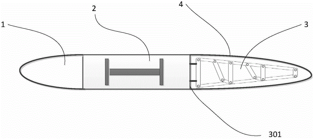
[0032] Such as Figure 1-Figure 4 As shown, the present embodiment provides a kind of aircraft wing, and this aircraft wing comprises wing leading edge 1, wing middle part 2, wing trailing edge 3, wing skin 4; Wherein, wing middle part 2 camber cannot Change, the camber of the wing trailing edge 3 is variable.

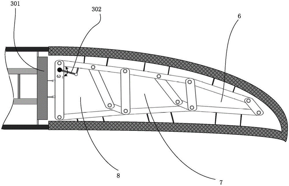
[0033] The wing trailing edge 3 includes a rear beam 301, three sets of closed-loop rod group units, and a drive mechanism 302; the rear beam 301 is connected to the rear end of the main beam; the closed-loop rod group unit is a planar rod group structure based on a 6R closed-loop unit, which has one degree of freedom;

[0034] Among them, such as Figure 4 As shown, three groups of closed-loop rod group units include a group of end units 6, a group of intermediate units 7, and a group of starting units 8; between end units 6;

[0035] The end unit 6 includes a first upper rail 601, a first lower rail 602, a right vertical bar 603, a first middle vertical bar 604, a...

Embodiment 2

[0043] Such as Figure 7 As shown, the difference between this embodiment and Embodiment 1 is that: the first lower cross bar is a straight bar, and the second lower cross bar is also a straight bar.

Embodiment 3

[0045] Such as Figure 8 As shown, the difference between this embodiment and Embodiment 1 is that: the upper end point of the first diagonal bar is hinged to the right end point of the second upper cross bar; the upper end point of the second inclined bar is hinged to the right end point of the third upper cross bar.


PUM


Abstract

The invention provides a complex-hinge transformable trailing edge mechanism based on planar linkage closed-loop units. The complex-hinge transformable trailing edge mechanism comprises at least three closed-loop linkage units and a drive mechanism. Each closed-loop linkage unit is a planar linkage structure based on a 6R closed-loop unit and has one freedom degree. The closed-loop linkage units include a tail-end unit, at least one middle unit and a starting-end unit which are parallelly arranged, and the middle units are arranged between the starting-end unit and the tail-end unit. Compared with the prior art, the complex-hinge transformable trailing edge mechanism has the advantages that the basic units of the complex-hinge transformable trailing edge mechanism are independent 6R closed-loop units, the units influence on another, and the output of the previous unit is the input of the next unit; the whole mechanism contains few linkages and is lightweight; the freedom degree of the whole mechanism is 1, the mechanism can be driven by only one drive motor, the weight of the mechanism is reduced, system control difficulty is lowered, and the gradual bending effect of a transformable wing is good due to the fact that multiple basic unit modules are used.

Description

technical field [0001] The invention relates to a deformable wing trailing edge mechanism with compound hinges based on a planar link closed-loop unit. Background technique [0002] Since the Wright Brothers invented the first airplane in human history on December 17, 1903, airplanes have played a very important role in human life. However, the wings of airplanes that are also used to generate lift cannot be as good as the wings of birds. It can stretch and dance freely, and cannot change the shape of its wings at different stages of flight like a bird. Developed countries in the aviation industry, led by the United States, began to study deformable wings in the 1990s in order to improve the aerodynamic characteristics of the wings, improve flight performance, enhance maneuverability, adaptability, etc., and make up for the shortcomings of traditional fixed-wing aircraft. For example, the F-111 stealth fighter of the United States, the leading edge and the trailing edge of ...

Claims


Application Information

Patent Timeline
Patent Type & Authority Applications(China)
IPC IPC(8): B64C3/44
CPCB64C3/44
Inventor 李兵李刚苗志怀
Owner HARBIN INST OF TECH SHENZHEN GRADUATE SCHOOL
Learn More